


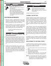
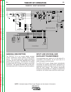
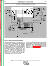
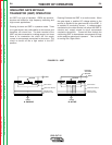
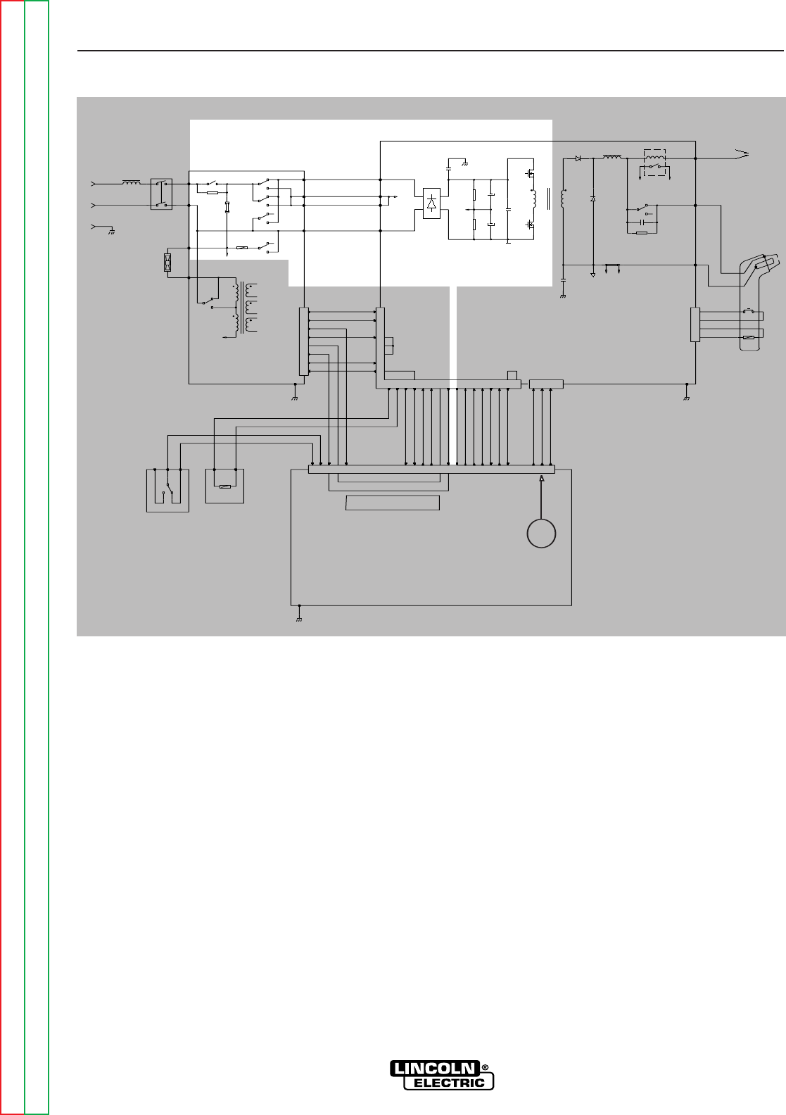
PRECHARGE AND PROTECTION
The input voltage is rectified by the input rectifier on
the inverter board. The resultant DC voltage is applied
to the filter capacitors through the automatic
reconnect of the input board. The input board also
contains precharging circuitry for the safe charging of
the input filter capacitors. Once the capacitors are
precharged the input board activates the RL3 input
relay. This connects full input power to the filter
capacitors. When the filter capacitors are fully
charged they act as power supplies for the IGBT
switching circuit. The IGBTs supply the main trans-
former primary winding with DC current flow.
The inverter board also monitors the filter capacitors
for overvoltage. If this occurs, the appropriate signal
is sent to the control board to disable the machines
output and to turn on the Thermal/Voltage Overload
status LED. See IGBT Operation discussion and
diagrams in this section.
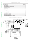
THEORY OF OPERATION
E-3 E-3
PRO-CUT 25
Return to Section TOC Return to Section TOC Return to Section TOC Return to Section TOC
Return to Master TOC Return to Master TOC Return to Master TOC Return to Master TOC
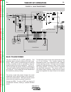
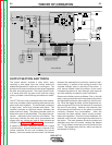
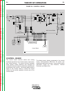
NOTE: Unshaded areas of Block Logic Diagram are the subject of discussion.
115/230/1/50/60 VAC
INPUT
CN1
2
1
4
3
5
6
7
8
300uH
L1
RL3
10/10W
R1
V2
V1
B
A
1A/250V
F1
RL2
RL2
RL2
AC
CP
CP
AC
L1
RL1
RL2
115VAC
230V
T1
115V
RL1
L1
15VAC
15VAC
SAFETY
+28VDC
SEC GND
OVLOAD
115/230
+12VDC
AC
CP
CP
AC
CN2
6
9
10
2
20
1516
+15Vrms
EV1
NO
COM
NC
12VDC
PS2
PS1
861793
OVLOAD
SEC GND
SAFETY
CN1
121814 1 11 4 13 7 19 242123 8 1 2 3
3
22
17
V+
+12VDC
+12VDC_SW
+8V_SW
SEC GND
OVLOAD
TRANSFER SW
TRANSFER
SOL 1 DRIVER
SOL 2 DRIVER
TRIGGER
OUTPUT
V_OUT
121814 7 15 4 11 5 16101213
5
4
POT_WIPER
23
POT_CW
22
POT_CCW
24
CP
15K/3W
R1
15K/3W
R2
1500uF/250V
C2a,b
1500uF/250V
C1a,b
C12
CP
C26
IRG4BC30W
Q1a,b,c
IRG4BC30W
Q2a,b,c
SEC
PRI
T2
C13
D10
D11
240uH
Lout
SHUNT
SH-
SH+
BS1
8A
+12VDC
TRANSFER
C14
6.8k/5W
R24
WRK
NZL (2)
EL (3)
CN3
2
1
3
4
12VDC
PT
WORK CLAMP
CN1
SW1
230VAC
FN1
+
+
RL1
Display LED's
Control Board
Output Control
Air
Solenoid
1
Purge
Switch
Input
Voltage Board
Main Inverter Board
Solenoid 2
FIGURE E.3 – PRECHARGE AND PROTECTION