


CAUTION
PRO-CUT 25
Return to Section TOC Return to Section TOC Return to Section TOC Return to Section TOC
Return to Master TOC Return to Master TOC Return to Master TOC Return to Master TOC
TROUBLESHOOTING & REPAIR
F-40 F-40
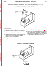
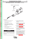
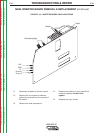
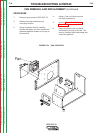
FIGURE F.18 – MAIN INVERTER BOARD REMOVAL
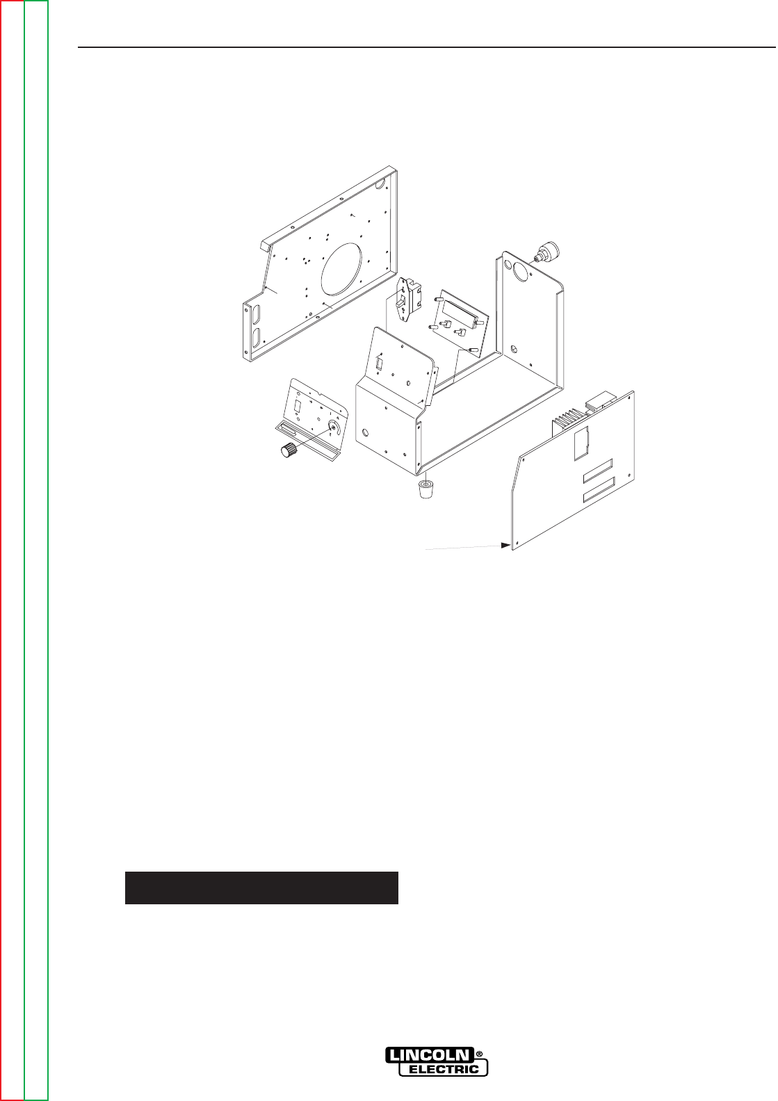
MAIN INVERTER BOARD REMOVAL & REPLACEMENT (continued)
PROCEDURE
1. Remove input power to PRO-CUT 25.
2. Remove carrying handle using a
4mm allen wrench.
3. Using a crescent wrench,
carefully remove the plastic nut from
around the pressure regulator located
on the top of the machine.
4. Using a 7mm nut driver, remove
the case wraparound.
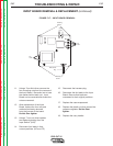
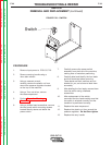
5. Perform Capacitor Discharge
Procedure.
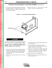
Be sure to follow the recommended static-free
methods for handling printed circuit boards.
Failure to do so can result in permanent damage
to the equipment.
6. Locate the Main Board, all associated
leads and plug connections.
7. Label the leads and note their positions
for reassembly.
8. Using a 7mm Nut driver, remove the
four nuts and washers located at the
corners of the main board. (This will
allow you to gently manipulate the board
for labeling and removal of all Leads.)
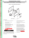
9. Remove the two harness plugs from
front top corner of board. Label
and remove the four single leads from
the rear top corner of board. Carefully
remove NZL, WRK, and EL leads from
lower front of board. Also remove
harness plug (J1). See Figure F.19.
10. Remove board.
LINCOLN
ELECTRIC
PRO-CUT 25
ON
OFF
PURGE
P
O
W
E
R
G
A
S
P
R
E
S
S
U
R
E
T
H
E
R
M
A
L
S
A
F
E
T
Y
!
RE
Q
U
IR
E
S
20
A
/1
15V
B
R
A
N
C
H
C
IR
C
U
IT
R
E
Q
U
IR
E
S
30
A/1
1
5
V B
R
A
N
C
H
C
IR
C
U
IT
2
5
2
0
1
5
1
2
Main Board