


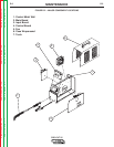
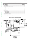
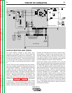
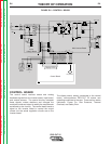
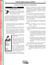

OUTPUT SECTION AND TORCH
The output section contains a relay which, upon
receiving a pilot signal from the control board will
enable the operation of a pilot arc or a cutting arc. The
printed circuit board mounted current sensor regulates
the pilot and cutting current. The output choke, which
is in series with both the pilot circuit and the cutting
circuit, provides current filtering to enhance arc stabil-
ity.
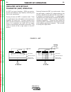
The PCT 20 torch uses a patented touch start mecha-
nism that provides superior starting performance over
other touch start systems. The torch head consists of
3 major parts: torch body, insulator and piston. The
insulator provides an electrical barrier between the
piston and torch body. The piston provides a path for
electrical current to the electrode. The piston also dri-
ves the electrode to the nozzle for arc initiation. The
torch body contains the main torch components: the
trigger, pilot arc, cutting arc, and air flow systems are
included. See Figure F.10 & G Section for more detail.
A copper nozzle with a patented internal swirl is used
to focus the arc. A small, precise hole in the end of the
nozzle constricts the arc and increases the current
density. As the air enters the torch head, it is directed
between the electrode and nozzle for maximum elec-
trode cooling. A portion of the cooling air exits in the
chamber through vents in the side of the nozzle. A
swirl texture located inside the bottom of the nozzle
increases the plenum air swirl strength, and improves
arc start reliability and parts-in-place verification.
Plasma arc initiation occurs as follows: First, in the idle
state, a spring inside the torch head pushes the piston
and electrode forward to make continuity with the noz-
zle. When the trigger is pulled, air flow begins and cre-
ates enough back force on the electrode to overcome
the force of the spring. However, the solenoid valve
allows enough forward force on the piston to maintain
continuity between the consumables. After this
continuity has been verified, output current is estab-
lished and regulated. Once the current stabilizes, the
solenoid valve turns off, removing the forward force on
the piston. The back pressure drives the piston and
electrode away from the nozzle, creating the plasma
arc. The air stream forces the arc out the orifice of the
nozzle. This appears as a pilot arc, which can then be
transferred for cutting.
THEORY OF OPERATION
E-5 E-5
PRO-CUT 25
Return to Section TOC Return to Section TOC Return to Section TOC Return to Section TOC
Return to Master TOC Return to Master TOC Return to Master TOC Return to Master TOC
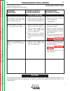
FIGURE E.5 – PLASMA OUTPUT SECTION AND TORCH
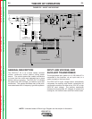
115/230/1/50/60 VAC
INPUT
CN1
2
1
4
3
5
6
7
8
300uH
L1
RL3
10/10W
R1
V2
V1
B
A
1A/250V
F1
RL2
RL2
RL2
AC
CP
CP
AC
L1
RL1
RL2
115VAC
230V
T1
115V
RL1
L1
15VAC
15VAC
SAFETY
+28VDC
SEC GND
OVLOAD
115/230
+12VDC
AC
CP
CP
AC
CN2
6
9
10
2
20
1516
+15Vrms
EV1
NO
COM
NC
12VDC
PS2
PS1
861793
OVLOAD
SEC GND
SAFETY
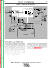
CN1
121814 1 11 4 13 7 19 242123 8 1 2 3
3
22
17
V+
+12VDC
+12VDC_SW
+8V_SW
SEC GND
OVLOAD
TRANSFER SW
TRANSFER
SOL 1 DRIVER
SOL 2 DRIVER
TRIGGER
OUTPUT
V_OUT
121814 7 15 4 11 5 16101213
5
4
POT_WIPER
23
POT_CW
22
POT_CCW
24
CP
15K/3W
R1
15K/3W
R2
1500uF/250V
C2a,b
1500uF/250V
C1a,b
C12
CP
C26
IRG4BC30W
Q1a,b,c
IRG4BC30W
Q2a,b,c
SEC
PRI
T2
C13
D10
D11
240uH
Lout
SHUNT
SH-
SH+
BS1
8A
+12VDC
TRANSFER
C14
6.8k/5W
R24
WRK
NZL (2)
EL (3)
CN3
2
1
3
4
12VDC
PT
WORK CLAMP
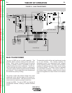
CN1
SW1
230VAC
FN1
+
+
RL1
Display LED's
Control Board
Output Control
Air
Solenoid
1
Purge
Switch
Input
Voltage Board
Main Inverter Board
Solenoid 2