


TROUBLESHOOTING & REPAIR
F-27 F-27
PRO-CUT 25
Return to Section TOC Return to Section TOC Return to Section TOC Return to Section TOC
Return to Master TOC Return to Master TOC Return to Master TOC Return to Master TOC
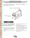
TORCH CONTINUITY AND SOLENOID TEST (continued)
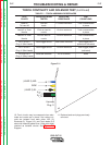
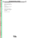
TABLE F.1 - TORCH ASSEMBLY RESISTANCES
TEST CIRCUIT(S) BEING EXPECTED TEST
POINTS TESTED RESISTANCE CONDITIONS
Lead #2 Pilot arc 1.5 ohms maximum Torch consumables
To Lead #3 leads in place
Lead #2 to Torch Pilot arc lead to 1.0 ohm maximum Torch consumables
Nozzle nozzle in place
Lead #3 to Torch Pilot arc lead to 1.0 ohm maximum Torch consumables
Nozzle nozzle in place
Pin 1 to Pin 2 Torch trigger circuit 100K ohms minimum Torch trigger NOT
Plug J1 (Red Leads) pulled (not activated)
Pin 1 to Pin 2 Torch trigger circuit 1.0 ohm maximum Torch trigger pulled
Plug J1 (Red Leads) (activated)
Pin 3 to Pin 4 Electrode Solenoid 45 to 55 ohms None
Plug J1 (Gray Leads)
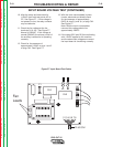
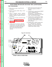
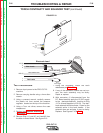
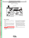
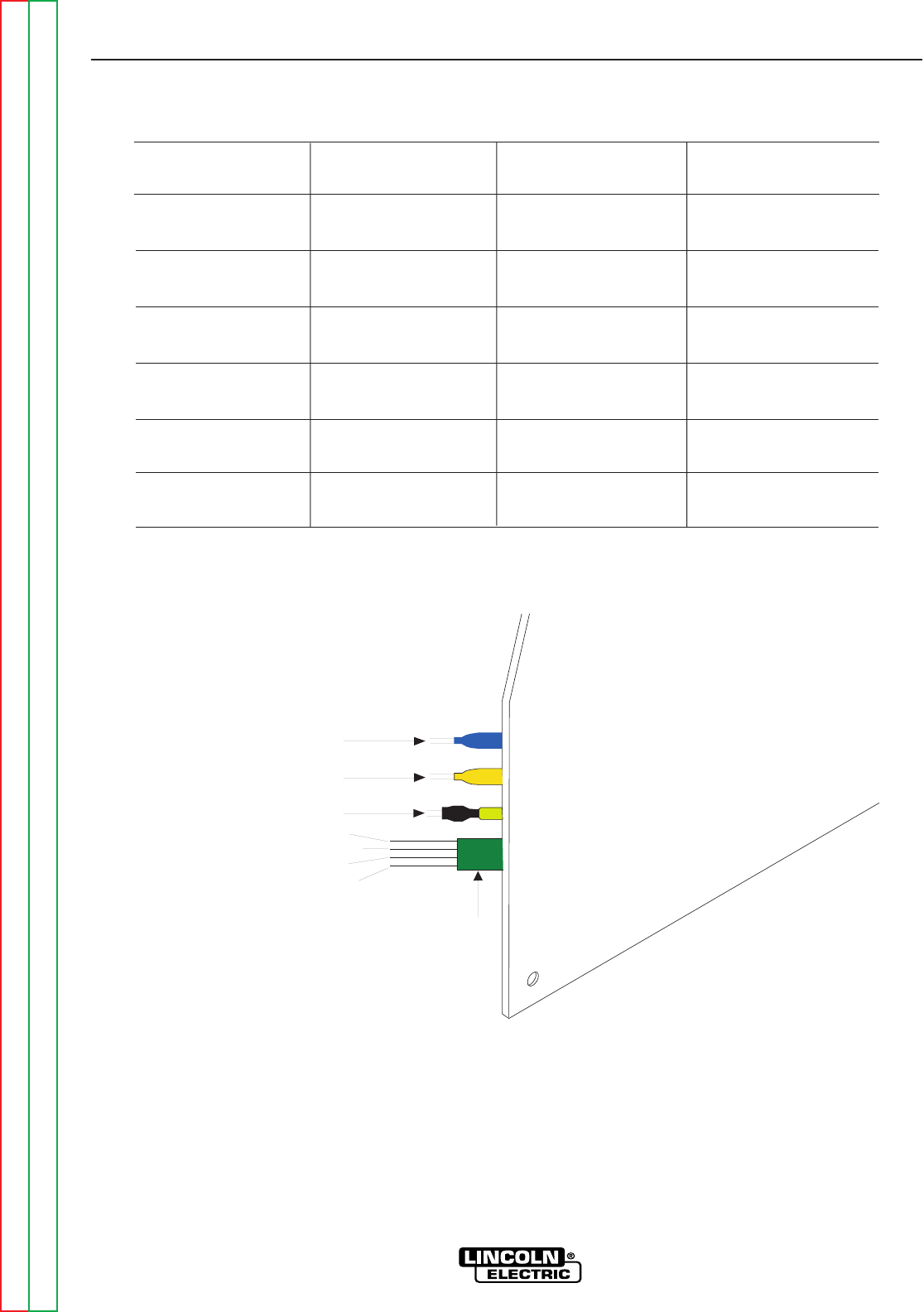
10. Torch circuits may be measured when elec-
trode and nozzle are in place if the various cir-
cuits are isolated from each other. NZL (2),
Electrode (3), Trigger (1,2), and Torch leads (3,4)
should all measure greater than 1 Meg ohm when
checked as isolated circuits. See Figure F.10
Diagram.
11. Replace leads and plugs previously
removed.
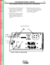
(LEAD 2) NZL
WRK
(LEAD 3) EL
Harness
Plug J1
1
2
3
4
Figure F.11