


Return to Section TOC Return to Section TOC Return to Section TOC Return to Section TOC
Return to Master TOC Return to Master TOC Return to Master TOC Return to Master TOC
TROUBLESHOOTING & REPAIR
F-26 F-26
PRO-CUT 25
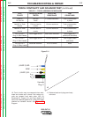
TORCH CONTINUITY AND SOLENOID TEST (continued)
TEST PROCEDURE
1. Remove input power to the PRO-CUT 25
machine.
2. Remove carrying handle using a 4mm allen
wrench.
3. Using a crescent wrench, carefully remove
the plastic nut from around the pressure
regulator located on the top of the machine.
4. Using a 7mm nut driver, remove the case
wraparound.
5. Perform the Capacitor Discharge
Procedure.
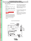
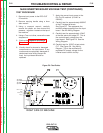
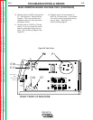
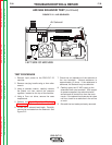
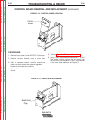
6. Remove Plug J1, Lead #2, and Lead #3 from
the Main Inverter Board. See Figure F.10
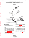
7. Using the ohmmeter, check the torch
resistances per Table F.1.
8. If any of the resistance checks are not cor-
rect, the torch assembly may be faulty.
Repair or replace.
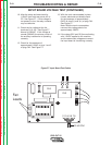
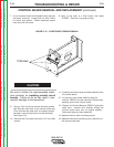
9. With connector J1 disconnected from the
P.C. Board carefully apply the 12 VDC supply
to the electrode solenoid. (positive to Plug
J1 Pin #4 and Negative to Pin #3). The elec-
trode solenoid should activate. Listen for the
solenoid action in the torch handle. If the
solenoid does not activate, it may be faulty.
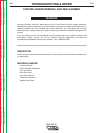
Replace. See Figures F.10 & F.11.
FIGURE F.10
(NZL)
WRK
(EL)
Harness
Plug
Plug J1
LEAD 3
LEAD 2
Red Leads
Blue Leads
Torch Solenoid
Vent Tube
Electrode Lead
Air Hose
White & Black Pairs
Connector
ELECTRODE
BODY (nozzle)
Electrode is
insulated from
Brass Body
outside
center
flex tubes
Pilot path / air tube
crimp
fitting
N.O.
Torch Trigger
EL (3)
3
4
NZL (2)
1
2