


THEORY OF OPERATION
E-4 E-4
PRO-CUT 25
Return to Section TOC Return to Section TOC Return to Section TOC Return to Section TOC
Return to Master TOC Return to Master TOC Return to Master TOC Return to Master TOC
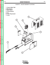
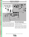
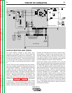
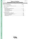
FIGURE E.4 – MAIN TRANSFORMER
115/230/1/50/60 VAC
INPUT
CN1
2
1
4
3
5
6
7
8
300uH
L1
RL3
10/10W
R1
V2
V1
B
A
1A/250V
F1
RL2
RL2
RL2
AC
CP
CP
AC
L1
RL1
RL2
115VAC
230V
T1
115V
RL1
L1
15VAC
15VAC
SAFETY
+28VDC
SEC GND
OVLOAD
115/230
+12VDC
AC
CP
CP
AC
CN2
6
9
10
2
20
1516
+15Vrms
EV1
NO
COM
NC
12VDC
PS2
PS1
861793
OVLOAD
SEC GND
SAFETY
CN1
121814 1 11 4 13 7 19 242123 8 1 2 3
3
22
17
V+
+12VDC
+12VDC_SW
+8V_SW
SEC GND
OVLOAD
TRANSFER SW
TRANSFER
SOL 1 DRIVER
SOL 2 DRIVER
TRIGGER
OUTPUT
V_OUT
121814 7 15 4 11 5 16101213
5
4
POT_WIPER
23
POT_CW
22
POT_CCW
24
CP
15K/3W
R1
15K/3W
R2
1500uF/250V
C2a,b
1500uF/250V
C1a,b
C12
CP
C26
IRG4BC30W
Q1a,b,c
IRG4BC30W
Q2a,b,c
SEC
PRI
T2
C13
D10
D11
240uH
Lout
SHUNT
SH-
SH+
BS1
8A
+12VDC
TRANSFER
C14
6.8k/5W
R24
WRK
NZL (2)
EL (3)
CN3
2
1
3
4
12VDC
PT
WORK CLAMP
CN1
SW1
230VAC
FN1
+
+
RL1
Display LED's
Control Board
Output Control
Air
Solenoid
1
Purge
Switch
Input
Voltage Board
Main Inverter Board
Solenoid 2
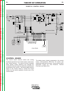
MAIN TRANSFORMER
The pair of IGBTs act as a switch assembly. This
assembly feeds a primary winding of the main trans-
former. When current is pulsed through this primary
winding, a resultant current is produced on the sec-
ondary winding of the main transformer. The DC cur-
rent flow through the primary winding is redirected or
“clamped” back to the filter capacitors when the IGBTs
are turned off. This is needed due to the inductance of
the transformer primary winding.
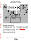
The primary current also passes through the current
transformer, which sends a signal to the control cir-
cuits of the inverter board. This signal and the control
circuits limit the maximum primary current flow
through the IGBTs. The pair of IGBT’s are fired at 15
microsecond intervals, creating a constant 66.6KHz
output.
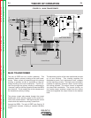
The secondary portion of the main transformer is made
up of one winding. This winding supplies the
electrode-to-nozzle and electrode-to-work voltages
and the resulting currents. This high current winding is
capable of supplying maximum output current during
the cutting process. The output current is regulated
via pulse width modulation. The control circuitry, on
the inverter board, receives a signal from the control
board and regulates the output current to the desired
level.