


TROUBLESHOOTING & REPAIR
F-19 F-19
PRO-CUT 25
Return to Section TOC Return to Section TOC Return to Section TOC Return to Section TOC
Return to Master TOC Return to Master TOC Return to Master TOC Return to Master TOC
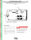
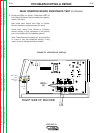
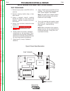
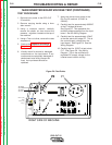
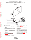
10. After the relays activate check for
115VAC from both test points AC to
CP. See Figure F.7. If this voltage is
not present or low, the relay contacts
may be defective.
11. Check the fan voltage at the fan
terminals (V1 & V2). See Figure F.7
Normal is 230VAC. If this voltage is
normal (230VAC) the primary circuit of
the auxiliary transformer is operating
correctly.
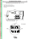
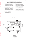
12. Check for the presence of
approximately 15VAC at pins 1 and 2
of plug CN1. See Figure F.7.
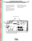
13. With the torch consumables in place
(nozzle, electrode and shield) check
for the presence of approximately
6VDC at pins 3(-) and 4(+) of plug CN1.
See Figure F.7.
Note: With the torch consumables
removed this voltage should be
approximately 26VDC.
14. If the relays (RL2 and RL3) are activating
with 115VAC applied to the machine
and the above test voltages are correct
the input board is functioning correctly.
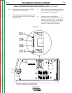
INPUT BOARD VOLTAGE TEST (CONTINUED)
A
B
RL2
RL3
F1
AC
AC
CP
V1
V2
PLUG CN1
1 2 3 4 5 6 7 8
Figure F.7 Input Board Test Points
Fan
Leads