


Return to Section TOC Return to Section TOC Return to Section TOC Return to Section TOC
Return to Master TOC Return to Master TOC Return to Master TOC Return to Master TOC
TROUBLESHOOTING & REPAIR
F-12 F-12
PRO-CUT 25
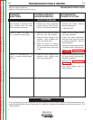
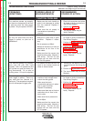
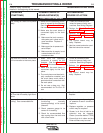
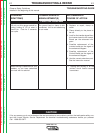
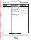
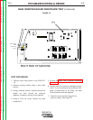
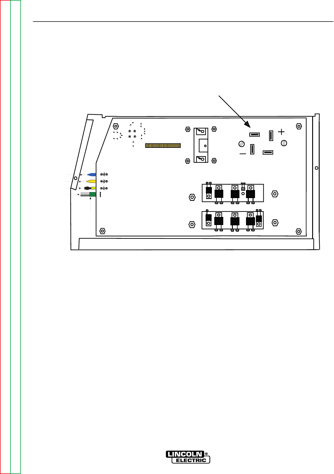
MAIN INVERTER BOARD RESISTANCE TEST (continued)
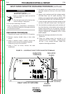
FIGURE F.2
TEST PROCEDURE
1. Remove main input power to the PRO-CUT
25.
2. Remove carrying handle using a 4mm allen
wrench.
3. Using a crescent wrench, carefully remove the
plastic nut from around the pressure
regulator located on the top of the machine.
4. Using a 7mm nut driver, remove the case
wraparound.
5. Perform the Input Filter Capacitor Discharge
Procedure detailed earlier in this section.
6. Visually check for burned or damaged compo-
nents. If any components are physically dam-
aged or determined to be faulty, the Main
Inverter Board should be replaced.
7. Check the input rectifier bridge (P1) for
shorts or opens. See Figure F.2
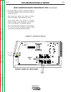
RIGHT SIDE OF MACHINE
(NZL)
WRK
(EL)
Harness
Plug
Plug J1
LEAD 3
LEAD 2
P1