


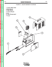
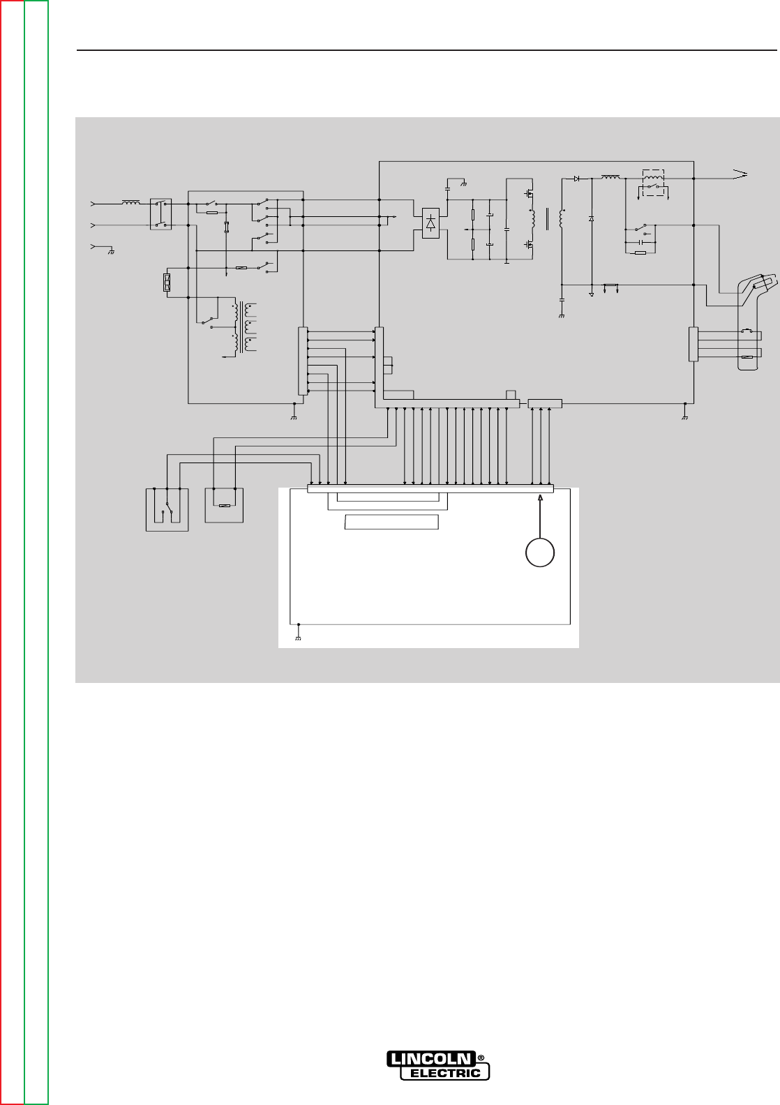
CONTROL BOARD
The control board receives status and analog
feedback signals from the inverter board, input board,
and various sensors. The control circuitry interprets
these signals, makes decisions and changes the
machines mode and output to satisfy the requirements
as defined by the circuitry. The control board sends a
signal to the inverter board to control the output
current but the actual regulation circuits are on the
inverter board.
The display board, directly connected to the control
board, communicates PRO-CUT 25 status and
operating conditions to the user. There are four status
indicators: Power On, Gas Pressure, Thermal
Overload, and Safety Error.
THEORY OF OPERATION
E-6 E-6
PRO-CUT 25
Return to Section TOC Return to Section TOC Return to Section TOC Return to Section TOC
Return to Master TOC Return to Master TOC Return to Master TOC Return to Master TOC
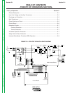
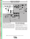
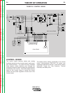
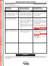
FIGURE E.6 – CONTROL BOARD
115/230/1/50/60 VAC
INPUT
CN1
2
1
4
3
5
6
7
8
300uH
L1
RL3
10/10W
R1
V2
V1
B
A
1A/250V
F1
RL2
RL2
RL2
AC
CP
CP
AC
L1
RL1
RL2
115VAC
230V
T1
115V
RL1
L1
15VAC
15VAC
SAFETY
+28VDC
SEC GND
OVLOAD
115/230
+12VDC
AC
CP
CP
AC
CN2
6
9
10
2
20
1516
+15Vrms
EV1
NO
COM
NC
12VDC
PS2
PS1
861793
OVLOAD
SEC GND
SAFETY
CN1
121814 1 11 4 13 7 19 2421 23 8 1 2 3
3
22
17
V+
+12VDC
+12VDC_SW
+8V_SW
SEC GND
OVLOAD
TRANSFER SW
TRANSFER
SOL 1 DRIVER
SOL 2 DRIVER
TRIGGER
OUTPUT
V_OUT
121814 7 15 4 11 5 16101213
5
4
POT_WIPER
23
POT_CW
22
POT_CCW
24
CP
15K/3W
R1
15K/3W
R2
1500uF/250V
C2a,b
1500uF/250V
C1a,b
C12
CP
C26
IRG4BC30W
Q1a,b,c
IRG4BC30W
Q2a,b,c
SEC
PRI
T2
C13
D10
D11
240uH
Lout
SHUNT
SH-
SH+
BS1
8A
+12VDC
TRANSFER
C14
6.8k/5W
R24
WRK
NZL (2)
EL (3)
CN3
2
1
3
4
12VDC
PT
WORK CLAMP
CN1
SW1
230VAC
FN1
+
+
RL1
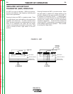
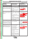
Display LED's
Control Board
Output Control
Air
Solenoid
1
Purge
Switch
Input
Voltage Board
Main Inverter Board
Solenoid 2