


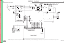

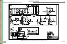
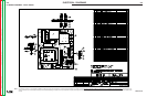

ELECTRICAL DIAGRAMS
G-3
PRO-CUT 25
WIRING DIAGRAM W/ADDITIONAL INFO
pressure
Schematic 98056 (SIPC 25)
Schematic 99016 ( SPA25)
Schematic 98044
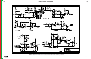
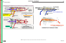
Purge Switch (n.o.)
Gas Psi
.
Thermo
Safety led
Input Power
8
vdc
when
open
for
correct
pressure
RL1
RL3
Auto
reconnect
card
RL1
(control bd
mounted)
50hz /60
hz
RPM’s 2700/ 3100
amps .13 / .12
runs all the time
Pcb
.
card
relay
Reconnect
pilot relay
+12 v
8vdc @ min
10-5
vdc
@ max.
(power supplies from
inverter bd.
for pot only!!)
This bd
generates 8 vdc
which get its input from
the inverter bd
. via the
12
vdc
on the inverter bd
.
8v is used on both
bds.
8vdc
(pip)
reset by turning off PC25
also
input overload
all LED’s come on
initally
then just the POWER led is lit
THERMO led stays lit for
approx
3 sec also at turn on.
12v=230
0v =115
+15Vrms
( reed )
( relay )
Soft start relay
3 to 5 sec delay
(12
vdc
)
Soft start resistor
( over heats on 208 input !)
Shown in 230
de-energized
+12 VDC
sw
supply is used for:
1. Output control (control).
& its ref bd. (invert)
2. Shunt feedback ( invert)
3. Transfer relay (invert & control)
4. Torch solenoid (
inv
& control)
5. LED supply
+8 VDC supply is used for:
1. Turn on PWM (invert)
2. PIP detect
ckt.(control)
3. Pilot arc timer (control)
4. Purge
ckt
button(control)
5. Drivers for LED logic (control)
6. Torch solenoid logic
ckt(control)
7. Air solenoid logic
ckts
& driver (control)
8. Transfer relay (invert) Logic &driver(control)
Represents:
board soldered to
a mother
bd
.
Represents:
relay soldered to
a mother
bd
.
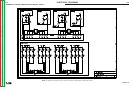
DC
REF bd
card
PWM
driver
card
PWM
card
reg
+12V
( pwm gate drive signal)
+12
vdc
+15Vrms
PT3
amp
shunt input
+12V
inverter bd
.
inverter bd
.
common for
trigger
pink
pink
230vac
Auto reconnect
ckt
.
PIP supply 20
vac
{
Supply for torch,&
main air solenoid .
12 V regulator
on inverter bd
.
Vs =OK
0v= over
load.
{
over
volts
signal
{
{
This is the voltage
reconnect for 110V
operation
(voltage
doubler
)
operating
freq
. 63
khz
/ 100khz
(PC 25) / (PC20)
All
thermo devices are on this
inverter board
primary current
feedback c.t.
primary c.t.
( air )
( torch)
Q4
Reco
nnect
mai
nrelay
+12V
Aux
fuse
OVL signal
+8 = on (from
control bd.)
isolated
+20
Vdc
for NO parts in place(pip)
+6
Vdc
with parts IN
4.7nf
4kv
4.7 f
4kv
To
pwm
chip
sec
thermo
PT2
(N.C.)
F.e.t.
thermo
PT1
(N.C.)
some
‘s
some
‘s
300
VDC
Mai
n
Cap
s.
to
nozzle
ckt
.
*does it work
in the other input
voltage 115v or 230 v ?
If it does, it is an
input
bd
.
Listen for relay to
click
in
after a 3 sec delay
On f
or 110v
ac
+8v = no output
6v = output
To
{
+12v =pilot
0 = cutting
To
{
+8v = open trigger to
Choke
Thermo
( PCT)
P
T3
(N.O.)
+ 12 from Control bd
.
Reed switch (BS1)
closes when cutting
current is drawn
To Control bd
.
400Vocv
100v pilot &cutting
25a @ 35% duty (115 input)
25a @ 60% duty (230 input)
12 to 25 amps range
3/8 max thickness @ 30 amp input
+8V
direct to control bd..
+12v = sol off
0v = sol on
Must be
a
PC 25 nozzle!
S22147-028
no drag cups either
!
try without.
Must be to within
1/8 ” to transfer to cut.
cutting
+12V_
sw
Transfer relay
(signal from
control
bd
.)
shown in pilot
2.2 f/400v
Must double hit
when first turned on
input ( safety feature)
or after
thermo
reset
not so in
preflow
.
Torch solenoid:
supply from inverter
bd
.
Control is from control
bd
.
45 to 55 ohms
Cuts for 3 sec then quits
(stuck in pilot mode )
or
pilot current is 1/2 of
cutting current
EV2
Trigger:
8v when open
reg
+8
vdc
+12V_sw
8V
i
nput
+8
comes “on” at turn on
for 3 sec.
“see” pip
ckt
inset detail
“see” pip
ckt
inset detail
Scaled
down
version
of
output
+12
V= ok
0v = overload
(choke thermo or input bd
.)
2 f
400v
RHRG30120
PILOT PATH
PIP PATH
CUTTING PATH
PIP
PILOT
CUTTING
choke
5
00
V
Must be within
+/- 10% of input.
Must be greater than 208v.
YES for Ranger 250 series
Commander 300, 400 ,500’s
Auto Reconnect Feature
Air
Guage
Supply pressure must be:
80 to 150
psi
with a flow
rate of no less than 4.0
cfm
(113 l/min.)
240
cfh
Set air pressure while in
purge
to
65
psi
.
comes on if
no gas
psi
.
( over volt detect )
CN1-3
CN1-7
Input bd
Inverter bd
Control bd
.
20
vac
***
Detail***
PIP (safety
ckt
.)
CN1-4
CN1-3
CN2-11
CN2-6
NZL
EL
+20 Vdc for NO parts
in place(pip)
+6
Vdc
with parts IN
LED
ckt.
10 K
torches of
15 or 25ft are ok
all
ckt
. commons
0 170
65
50 150
Ckt
.
Ckt
.
Display
bd & Driver bd
.
indicates that
the +12 on inverter
bd
is up ( not the +8)
“see” pip
ckt
inset detail
PILOT
Current
is 12 amps
Typical input current draw:
115v 25A/35% = 37.7A
20A/60% = 26.7A
230v 25A/60% = 19A
20A/100%=15A
13
2 . 5
K
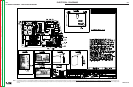
PRO CUT 25
file: procut25.pp
3-11-02 3-6-03
3-20-02
Closes @ 43.5
psi
(3bars)
Opens@ 37.7 to 42
psi
(2.6 to 2.9 bars)
when in 230
115vac
115vac
when in 115
when in 115
R
e
m
o
ve
e
le
c
t
r
od
e
.
C
h
e
c
k
f
o
r
s
h
o
r
t
s
&
o
p
e
n
s
t
o
ot
h
e
r
l
ea
d
s
G-3
NOTE: This diagram is for reference only. It may not be accurate for all machines covered by this manual.
Return to Section TOC Return to Section TOC Return to Section TOC Return to Section TOC
Return to Master TOC Return to Master TOC Return to Master TOC Return to Master TOC