


PRO-CUT 25
Return to Section TOC Return to Section TOC Return to Section TOC Return to Section TOC
Return to Master TOC Return to Master TOC Return to Master TOC Return to Master TOC
TROUBLESHOOTING & REPAIR
F-44 F-44
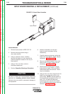
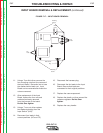
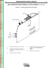
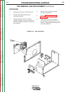
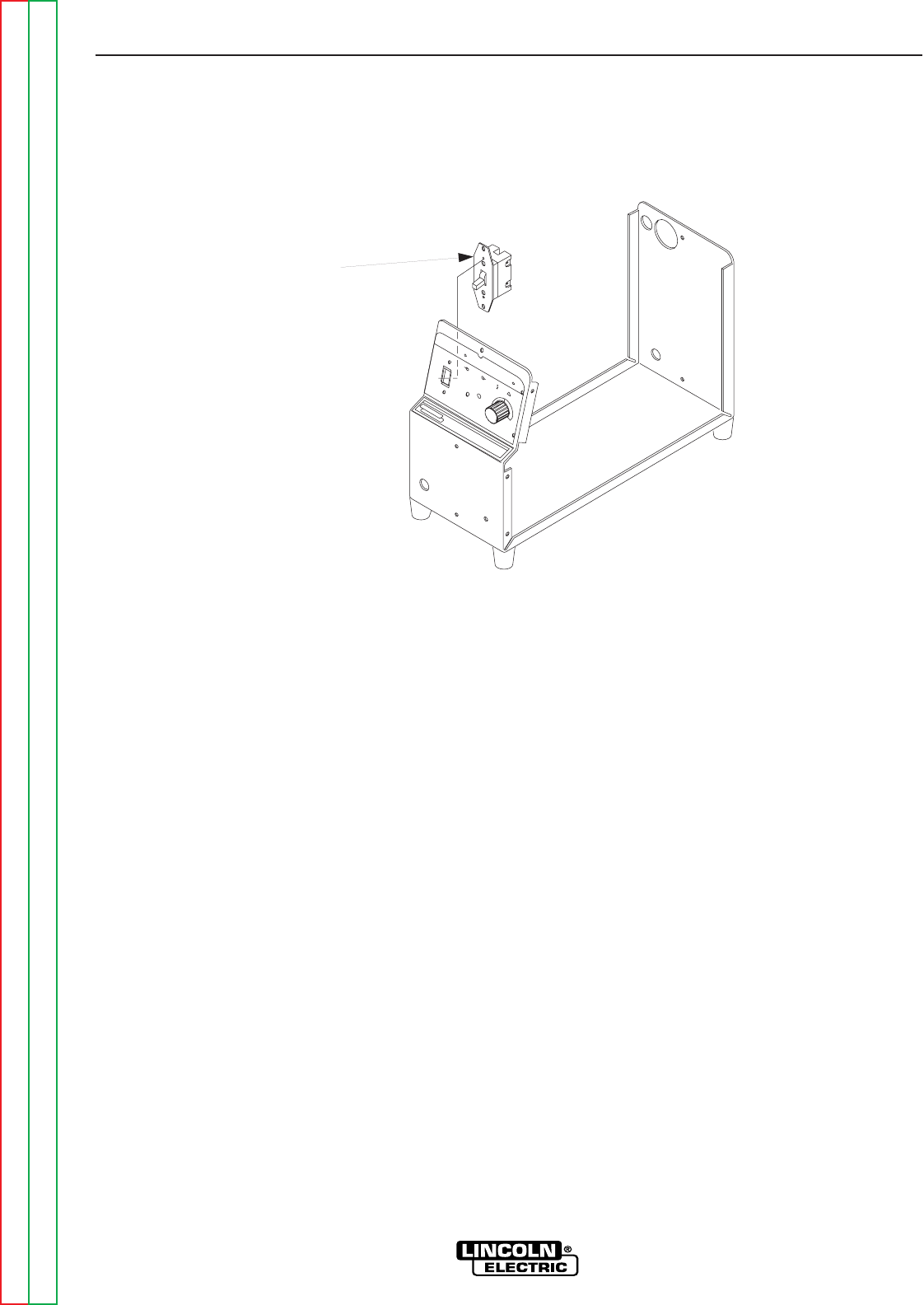
FIGURE F.20 – SWITCH
L
IN
C
O
L
N
E
L
E
C
T
R
IC
PRO-CUT 25
O
N
O
FF
PU
R
G
E
P
O
W
E
R
G
A
S
P
R
E
S
S
U
R
E
T
H
E
R
M
A
L
S
A
F
E
T
Y
!
R
E
Q
U
I
R
E
S
2
0
A
/
1
1
5
V
B
R
A
N
C
H
C
I
R
C
U
I
T
R
E
Q
U
I
R
E
S
3
0
A
/
1
1
5
V
B
R
A
N
C
H
C
I
R
C
U
I
T
2
5
2
0
1
5
Switch
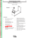
SWITCH
REMOVAL AND REPLACEMENT (continued)
PROCEDURE
1. Remove input power to PRO-CUT 25.
2. Remove carrying handle using a
4mm allen wrench.
3. Using a crescent wrench,
carefully remove the plastic nut from
around the pressure regulator located
on the top of the machine.
4. Using a 7mm nut driver, remove
the case wraparound.
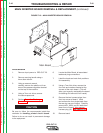
5. Perform Capacitor Discharge
Procedure.
6. Using a phillips head screwdriver, remove
the two power switch mounting screws
located directly above and below the
power switch.
7. Carefully remove the power switch
assembly from the front of the machine,
making note of insulation positioning.
8. Carefully label and identify the four leads
and their terminals before removing.
These leads and their positions are not
labeled for you, so be sure to label them
accurately
9. After labeling the four leads, remove them
from the switch using a flathead
screwdriver.
10. After replacement of the switch,
reconnect the four leads making sure that
the switch is oriented correctly and the
insulation is positioned correctly.
11. Replace the case wraparound
12. Replace the plastic nut from around the
pressure regulator. Do Not Over tighten.
13. Replace the carry handle