


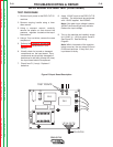

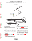


TEST PROCEDURE
1. Remove input power to the PRO-CUT
25 machine.
2. Remove carrying handle using a 4mm
allen wrench.
3. Using a crescent wrench, carefully
remove the plastic nut from around the
pressure regulator located on the top of
the machine.
4. Using a 7mm nut driver, remove the case
wraparound.
5. Perform the Capacitor Discharge
Procedure detailed earlier in this
section.
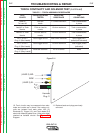
6. Visually check for burned or damaged
components on the input board. If any
components are physically damaged or
determined to be faulty (except the
fuse) the input board should be
replaced.
7. Apply the correct input power to the
Pro-Cut 25 machine. (115VAC or
230VAC)
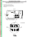
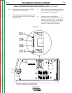
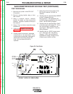
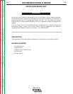
8. Carefully test for approximately 300VDC
at the P1 bridge terminals.
See Figure F.8. This represents the
rectified voltage supplied from the input
board. See the Wiring Diagram.
9. Carefully test for approximately 15VAC
at the test points on bridge P2. This is
the control supply voltage from the
input board. See Figure F.8. See the
Wiring Diagram.
10. Carefully test for 12VDC at test points
C17. See Figure F.8. See Wiring
Diagram. This is the rectified and
regulated DC supply voltage for the
inverter board control circuitry.
TROUBLESHOOTING & REPAIR
F-22 F-22
PRO-CUT 25
Return to Section TOC Return to Section TOC Return to Section TOC Return to Section TOC
Return to Master TOC Return to Master TOC Return to Master TOC Return to Master TOC
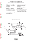
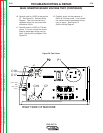
MAIN INVERTER BOARD VOLTAGE TEST (CONTINUED)
RIGHT SIDE OF MACHINE
(NZL)
WRK
(EL)
Harness
Plug
Plug J1
LEAD 3
LEAD 2
P1
P2
C17
P2
C7
C18
C19
AC
AC
+
+
+
Figure F.8. Test Points