


PRO-CUT 25
Return to Section TOC Return to Section TOC Return to Section TOC Return to Section TOC
Return to Master TOC Return to Master TOC Return to Master TOC Return to Master TOC
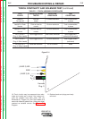
7. A nut is located under the red plastic piece that you
previously removed. Loosen this nut with a 6mm
nut driver and remove. Plastic alignment spacer
may come off with knob.
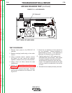
8. Next to the knob is a Red button that reads
“PURGE”. Remove it by gently pulling.
Be sure to follow the recommended static-
free methods for handling printed circuit
boards. Failure to do so can result in per-
manent damage to the equipment.
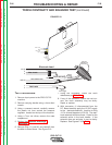
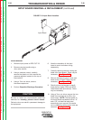
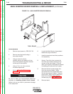
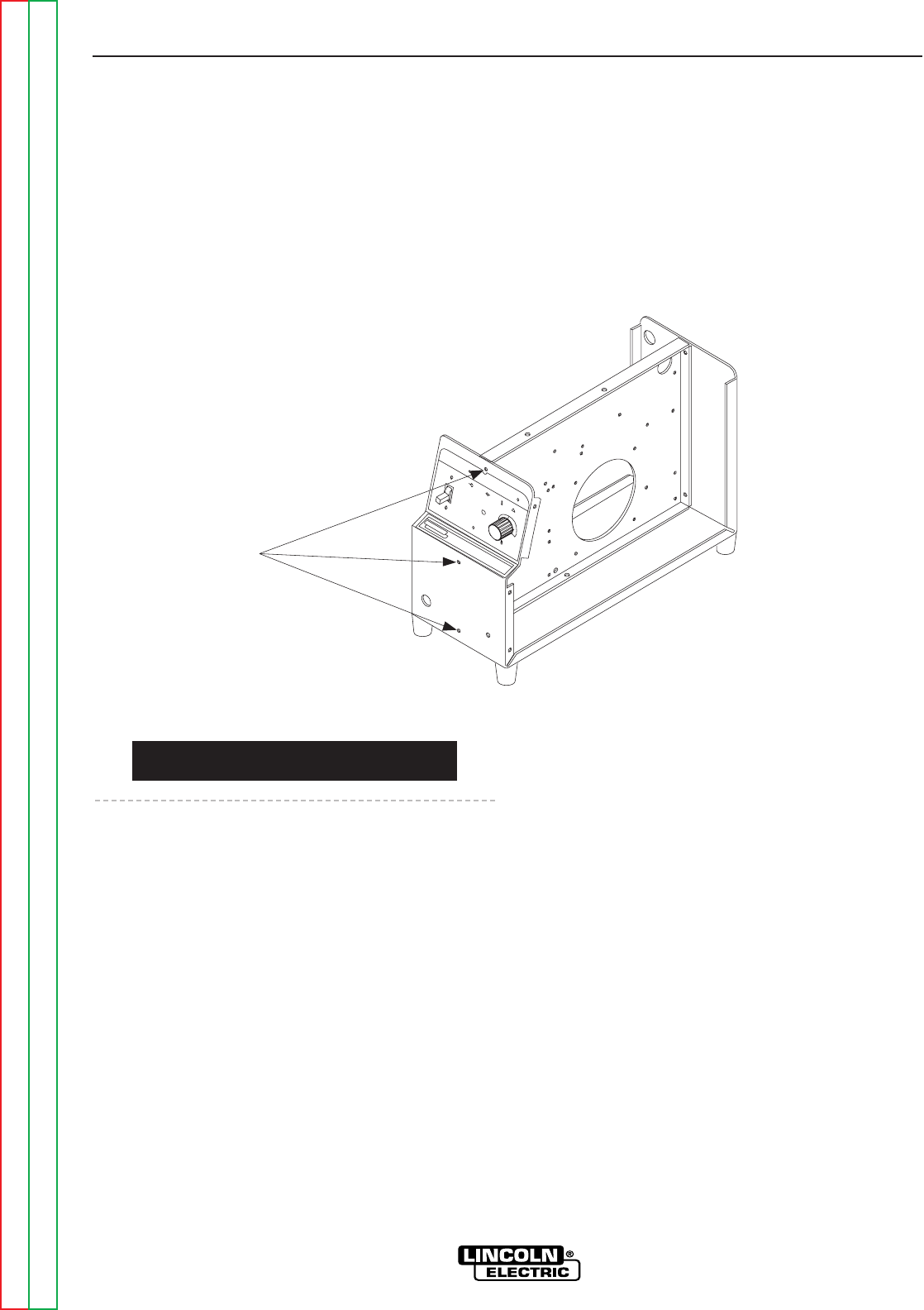
9. Using a 7mm nut driver remove the three screws
that hold the case front to the central metal wall.
(This will allow the case front to be gently pulled
forward so the Control board can be removed.)
See Figure F.15.
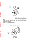
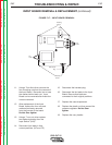
10. Remove the Four allen bolts with a 2.5 mm allen
wrench.
11. Carefully remove the plug and lead assembly from
the control board.
12. At this point, the control board is ready for
removal. GENTLY pull the case front forward and
carefully remove the Control board.
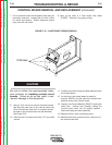
13. Replace the Control Board by GENTLY pulling the
case front forward and carefully sliding the
Control board back into its original position .
Reconnect plug and lead assembly.
14. Replace the four allen mounting screws.
15. Replace the screws connecting the case front to
the central metal wall.
TROUBLESHOOTING & REPAIR
F-33 F-33
L
IN
C
O
L
N
E
L
E
C
T
R
IC
PRO-CUT 25
O
N
O
FF
PU
R
G
E
P
O
W
E
R
G
A
S
P
R
E
S
S
U
R
E
T
H
E
R
M
A
L
S
A
F
E
T
Y
!
R
E
Q
U
I
R
E
S
2
0
A
/
1
1
5
V
B
R
A
N
C
H
C
I
R
C
U
I
T
R
E
Q
U
I
R
E
S
3
0
A
/
1
1
5
V
B
R
A
N
C
H
C
I
R
C
U
I
T
2
5
2
0
1
5
3 Screws
FIGURE F.15 - CASE FRONT SCREW REMOVAL
CONTROL BOARD REMOVAL AND REPLACEMENT (continued)
CAUTION