


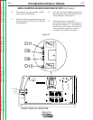

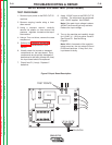

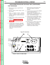
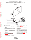

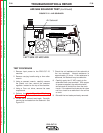

10. Carefully test for 12VDC at test points
C7. See Figure F.9. See the Wiring
Diagram. This is the rectified and
regulated supply for the pulse width
modulation circuit.
11. Carefully test for 12VDC at C18 test
points. If it is not correct the control
board or associated wiring may be
faulty. See the Wiring Diagram. See
Figure F.9.
12. Carefully check for the presence of
8VDC at C19 test points. If not correct
the control board or associated wiring
may be faulty. See Figure F.9.
See the Wiring Diagram.
TROUBLESHOOTING & REPAIR
F-23 F-23
PRO-CUT 25
Return to Section TOC Return to Section TOC Return to Section TOC Return to Section TOC
Return to Master TOC Return to Master TOC Return to Master TOC Return to Master TOC
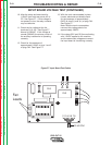
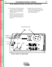
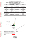
MAIN INVERTER BOARD VOLTAGE TEST (CONTINUED)
RIGHT SIDE OF MACHINE
(NZL)
WRK
(EL)
Harness
Plug
Plug J1
LEAD 3
LEAD 2
P1
P2
C17
P2
C7
C18
C19
AC
AC
+
+
+
+
+
Figure F.9 Test Points