


Return to Section TOC Return to Section TOC Return to Section TOC Return to Section TOC
Return to Master TOC Return to Master TOC Return to Master TOC Return to Master TOC
PRO-CUT 25
TROUBLESHOOTING & REPAIR
F-5 F-5
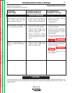
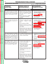
TROUBLESHOOTING GUIDE Observe Safety Guidelines
detailed in the beginning of this manual.
PROBLEMS
(SYMPTOMS)
POSSIBLE AREAS OF
MISADJUSTMENT(S)
RECOMMENDED
COURSE OF ACTION
FUNCTION PROBLEMS
The machine powers up properly,
but there is no response (no air flow
or pilot arc) when the torch trigger
is pulled. Only the power LED is lit.
1. Make sure the torch handle or
cable is not damaged or pulled
from the machine. Replace if
necessary.
2. Make sure the air supply is
converted and operating
properly.
1. Check all connectors and wires
for loose or faulty connections.
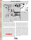
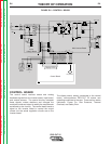
See Wiring Diagram.
2. Perform the Air/Gas
Solenoid Test.
3. The control board may be
faulty. Replace.
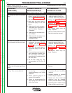
The machine powers up properly,
but only air flows when the torch
trigger is pulled; no pilot arc is
established.
1. Make sure the torch consum-
ables are in place and in good
condition. Replace if neces-
sary.
2. Set air pressure at 65psi.
3. Make sure there are no kinks or
restrictions for air flow in the
torch cable.
4. Make sure that the correct size
nozzle is being used. Must be a
.028 orifice. Pro-Cut 55 size
nozzles will not work with the
Pro-Cut 25 system.
1. Check all connectors and wires
for loose or faulty connections.
See Wiring Diagram.
2 Perform the Torch Continuity
and Solenoid Test.
3. Perform the Main Inverter
Board Voltage and
Resistance Tests.
4. The control board may be
faulty. Replace.
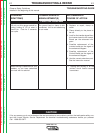
The machine powers up properly,
and cuts OK with 230 input
applied. With 115 applied the pilot
arc ignites but goes out when cut-
ting commences. Or, no pilot or
cutting when 115 input is supplied.
1. CP leads to its terminal from the
input to the inverter board are
loose or disconnected.
1. Reconnect the leads to its cor-
rect terminal per the wiring dia-
gram.
2. Perform the Input Board Test.
3. The input board may be faulty.
Replace.
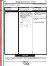
The air begins to flow when the
torch trigger is pulled. There is a
very brief pilot arc. (Normal is 3
Seconds.) The sequence is repeat-
ed with subsequent trigger pulls.
1. Check the input voltage at the
machine. Input voltage must
match the rating plate.
2. Make sure the torch
consumable parts are in place
and in good condition.
Replace if necessary.
3. Make sure there are no kinks or
restrictions for air flow in the
torch cable.
4. Make sure the air pressure is
set at 65psi.
5. Make sure that the correct size
nozzle is being used. Must be a
.028 orifice. Pro-Cut 55 size
nozzles will not work with the
PC 25 system.
1. Check all connectors and wires
for loose or faulty connections.
See Wiring Diagram.
2. Perform the Main Inverter
Board Voltage and
Resistance Tests.
3. The control board may be
faulty. Replace.