


Return to Section TOC Return to Section TOC Return to Section TOC Return to Section TOC
Return to Master TOC Return to Master TOC Return to Master TOC Return to Master TOC
PRO-CUT 25
TROUBLESHOOTING & REPAIR
F-37 F-37
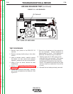
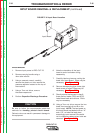
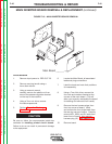
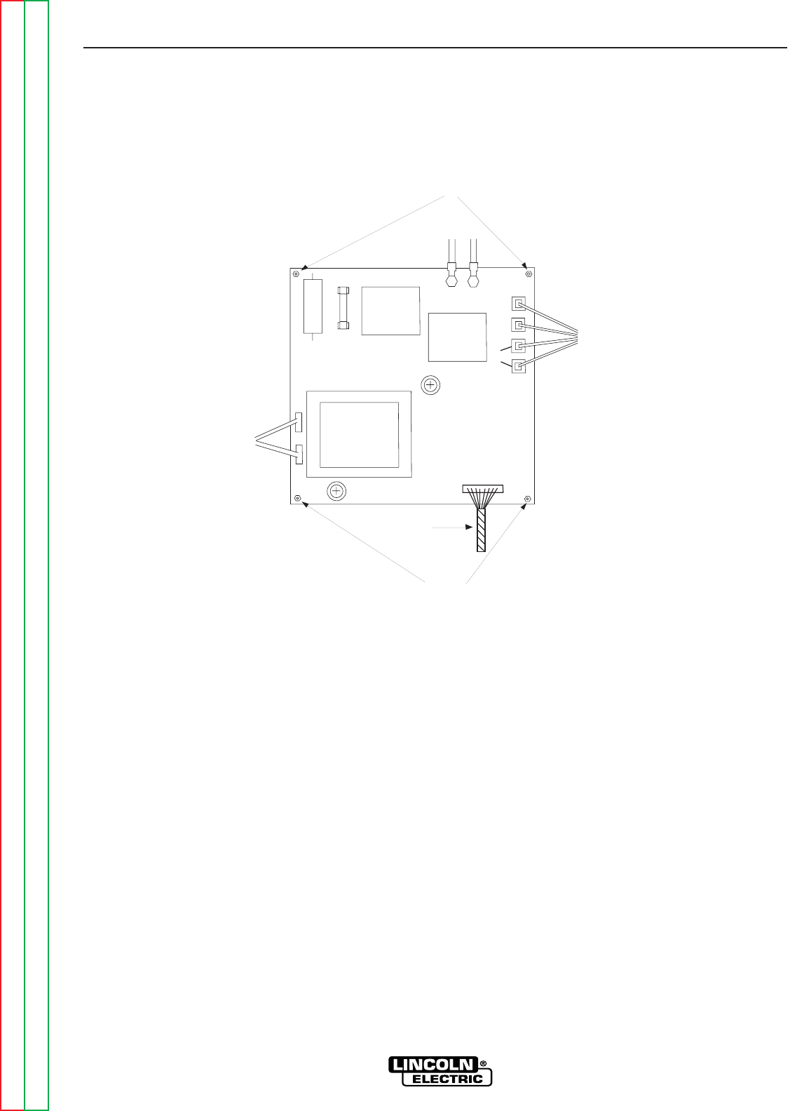
FIGURE F.17 – INPUT BOARD REMOVAL
Fan
Leads
Four
Leads
Switch
Leads
Mounting
Screws
Multi-colored
Plug
Mounting
Screws
A
B
AC
AC
CP
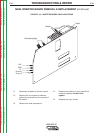
INPUT BOARD REMOVAL & REPLACEMENT (continued)
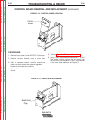
11. Using a 7mm Nut driver, remove the
four mounting nuts from the corners of
the Input Board. Be careful not to lose
the washer behind each nut. Input
Board can be removed after these four
nuts are removed.
12. After replacement of the Input
Board, replace the four nuts and
washers previously removed
from the corners of the board.
Do Not Over tighten.
13. Using a 7 mm nut driver replace
two leads originating from the
Input Switch. (A+B)
14. Reconnect four leads in their
correct positions. (AC and CP)
15. Reconnect the harness plug.
16. Reconnect the fan leads to the Input
Board. Be sure that leads are
connected to their original positions.
17. Replace the case wraparound.
18. Replace the plastic nut from around the
pressure regulator. Do Not Over
tighten.
19. Replace the carry handle.