


Return to Section TOC Return to Section TOC Return to Section TOC Return to Section TOC
Return to Master TOC Return to Master TOC Return to Master TOC Return to Master TOC
TROUBLESHOOTING & REPAIR
F-10 F-10
PRO-CUT 25
ELECTRIC SHOCK can kill.
• Have an electrician install and service
this equipment.
• Turn the input power off at the fuse box
before working on equipment.
• Do not touch electrically hot parts.
• Prior to performing preventative maintenance,
perform the following capacitor discharge procedure
to avoid electric shock.
DISCHARGE PROCEDURE
1. Remove input power to the PRO-CUT 25 machine.
2. Remove carrying handle using a 4mm allen
wrench.
3. Using a crescent wrench, carefully remove the
plastic nut from around the pressure regulator
located on the top of the machine.
4. Using a 7mm nut driver, remove the case
wraparound.
5. Be careful not to make contact with the capacitor
terminals located at the top of the main inverter
Board.
6. Obtain a high resistance and high wattage resistor
(25-1000 ohms and 25 watts minimum). This
resistor is not supplied with machine. NEVER USE
A SHORTING STRAP FOR THIS PROCEDURE.
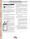
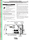
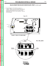
7. Locate the eight capacitor terminals located at the
top rear of the main inverter board. See Figure F.1
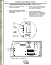
8. Use electrically insulated gloves and insulated pli-
ers. Hold the body of the resistor and connect the
resistor leads across the two capacitor terminals.
Hold the resistor in place for 10 seconds. DO NOT
TOUCH CAPACITOR TERMINALS WITH YOUR
BARE HANDS.
9. Repeat the discharge procedure for the other
capacitors.
10. Check the voltage across the terminals of all
capacitors with a DC voltmeter. Voltage should
be zero. If any voltage remains, repeat this
capacitor discharge procedure.
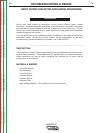
WARNING
CAPACITOR
TERMINALS
POWER
RESISTOR
INSULATED
GLOVES
INSULATED
PLIERS
RIGHT SIDE OF MACHINE
FIGURE F.1 – LOCATION OF INPUT FILTER CAPACITOR TERMINALS
INPUT FILTER CAPACITOR DISCHARGE PROCEDURE (continued)