


TROUBLESHOOTING & REPAIR
F-66 F-66
V350-PRO
Return to Section TOC Return to Section TOC Return to Section TOC Return to Section TOC
Return to Master TOC Return to Master TOC Return to Master TOC Return to Master TOC
ADVANCED PROCESS PANEL
REMOVAL AND REPLACEMENT (continued)
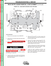
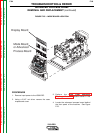
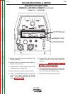
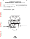
FIGURE F.27.. – CASE FRONT
9. Remove plug #J33 from the remote board. See
the Wiring Diagram.
10. Open the cover of the weld mode display on
the front of the machine.
11. Using a 5/16” nut driver, remove the three 5/16”
screws as shown in Figure F.27.
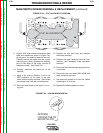
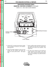
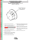
12. Place both knobs in the six o’clock position.
13. Using a small flathead screwdriver, loosen the
screw in the “Select” knob and the “Adjust”
knob. The knobs should slide off of their
shafts. See Figure F.28.
14. Using a 9/16” wrench remove the nuts and their
washers behind the two knobs previously
removed.
15. Perform the Remote Board Removal
Procedure. (Start at step #10)
16. Using a phillips head screwdriver remove the
two phillips head mounting screws at the bot-
tom of the Advanced Process board.
17. Remove the Advanced Process board.
REMOTE
ON
REMOTE
LOCAL
WELD TERMINALS
OUTPUT
CONTROL
SELECT SELECT
MPS
A
OLTS
V
MEMOR
MEMOR
Y BUTT
BUTT
ON
ON
SELECT
SELECT
ATTRIBUTE
TTRIBUTE
ADJUST
ADJUST
ATTRIBUTE
TTRIBUTE
SELECT
SELECT
KNOB
KNOB
_
+
5/16" Screws
Adjust Knob
Select Knob