


TROUBLESHOOTING & REPAIR
AUXILIARY TRANSFORMER NO.1 TEST (continued)
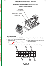
F-35 F-35
V350-PRO
Return to Section TOC Return to Section TOC Return to Section TOC Return to Section TOC
Return to Master TOC Return to Master TOC Return to Master TOC Return to Master TOC
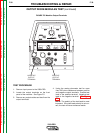
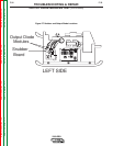
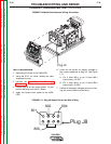
7. Carefully apply the correct input voltage to the
V350-PRO and check for the correct sec-
ondary voltages per table F.4. Make sure the
reconnect jumper lead and switch are config-
ured correctly for the input voltage being
applied. Make sure circuit breaker (CB3) is
functioning properly.
NOTE: The secondary voltages will vary if the
input line voltage varies.
8. If the correct secondary voltages are present,
the auxiliary transformer is functioning proper-
ly. If any of the secondary voltages are miss-
ing or low, check to make certain the primary
is configured correctly for the input voltage
applied. See Wiring Diagram.
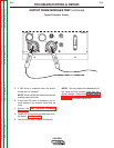
High voltage is present at primary of
Auxiliary Transformer.
9. If the correct input voltage is applied to the
primary, and the secondary voltage(s) are not
correct, the auxiliary transformer may be
faulty.
10. Remove the input power to the V350-PRO.
11. Install the case wraparound cover using a
5/16” nut driver.
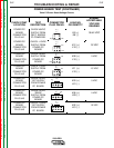
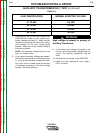
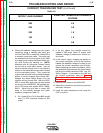
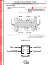
TABLE F.4
WARNING
LEAD IDENTIFICATION
NORMAL EXPECTED VOLTAGE
31 TO 532
115 VAC
42 TO 541
24 TO 541
42 VAC
24 VAC
28 VAC
54 TO 541