


PROCEDURE
1. Remove input power to the V350-PRO.
2. Using a 5/16” nut driver remove the case wrap-
around cover.
3. Perform the Input Filter Capacitor Discharge
Procedure detailed earlier in this section.
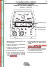
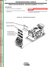
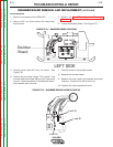
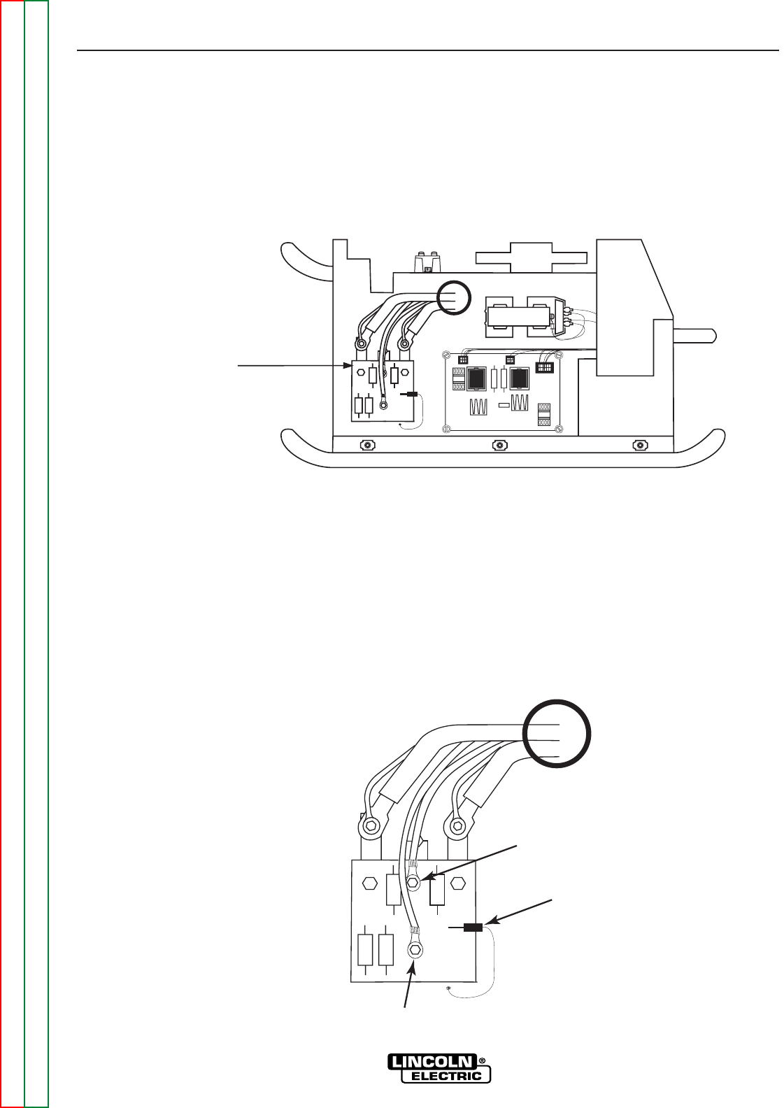
4. Locate the snubber board.. See Figure F.32.
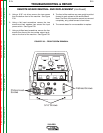
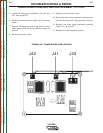
5. Remove small lead #B1 from the board. See
Figure F.33.
6. Remove the four bolts using a 7/16” socket. Two
of these bolts have leads #30 and #10 connected
to them. Note the position of all leads and associ-
ated washers upon removal.
7. Carefully remove the snubber board.
8. Replace the snubber board.
9. Replace the bolts, leads, and washers previously
removed. Torque bolt to 30-40 Inch Lbs.
10. Replace the case wraparound cover.
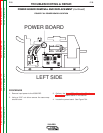
TROUBLESHOOTING & REPAIR
F-74 F-74
V350-PRO
Return to Section TOC Return to Section TOC Return to Section TOC Return to Section TOC
Return to Master TOC Return to Master TOC Return to Master TOC Return to Master TOC
SNUBBER BOARD REMOVAL AND REPLACEMENT (continued)
LEFT SIDE
Snubber
Board
FIGURE F.32. – SNUBBER BOARD LOCATION
Lead B1
Lead 30
Lead 20
FIGURE F.33. – SNUBBER BOARD LEADS (CLOSE UP)