


INSULATED GATE BIPOLAR
TRANSISTOR (IGBT)
OPERATION
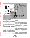
An IGBT is a type of transistor. IGBT are semiconduc-
tors well suited for high frequency switching and high
current applications.
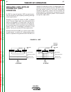
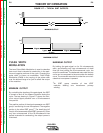
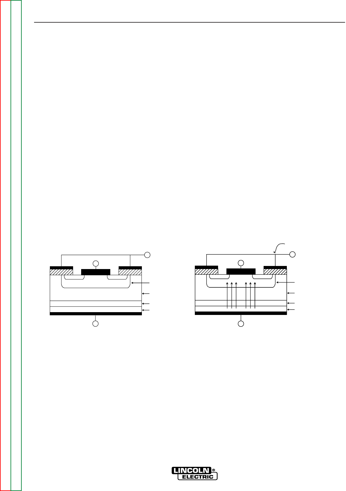
Example A in Figure E.6 shows an IGBT in passive
mode. There is no gate signal, zero volts relative to the
source, and therefore, no current flow. The drain ter-
minal of the IGBT may be connected to a voltage sup-
ply; but since there is no conduction, the circuit will not
supply current to components connected to the
source. The circuit is turned OFF like a light switch.
Example B shows the IGBT in an active mode. When
the gate signal , a positive DC voltage relative to the
source, is applied to the gate terminal of the IGBT, it is
capable of conducting current. A voltage supply con-
nected to the drain terminal will allow the IGBT to con-
duct and supply current to the circuit components
coupled to the source. Current will flow through the
conducting IGBT to downstream components as long
as the positive gate signal is present. This is similar to
turning ON a light switch.
THEORY OF OPERATION
E-7 E-7
V350-PRO
Return to Section TOC Return to Section TOC Return to Section TOC Return to Section TOC
Return to Master TOC Return to Master TOC Return to Master TOC Return to Master TOC
FIGURE E.6 – IGBT
DRAIN
SOURCE
GATE
INJECTING LAYER
BUFFER LAYER
DRAIN DRIFT REGION
BODY REGION
p +
n +
n -
p
n + n +
DRAIN
SOURCE
GATE
INJECTING LAYER
BUFFER LAYER
DRAIN DRIFT REGION
BODY REGION
p +
n +
n -
p
n + n +
POSITIVE
VOLTAGE
APPLIED
B. ACTIVE
A. PASSIVE