


V350-PRO
Return to Section TOC Return to Section TOC Return to Section TOC Return to Section TOC
Return to Master TOC Return to Master TOC Return to Master TOC Return to Master TOC
TROUBLESHOOTING & REPAIR
F-71 F-71
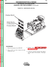
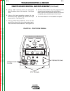
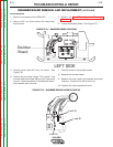
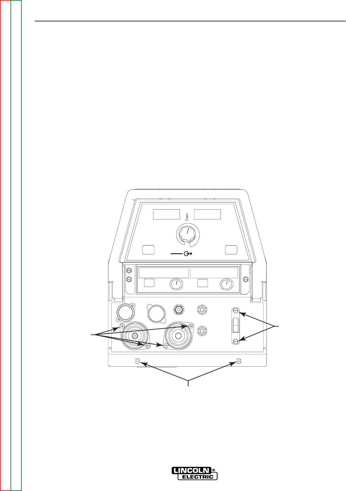
REMOTE BOARD REMOVAL AND REPLACEMENT (continued)
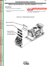
5. Using a 5/16” nut driver remove the two screws
from the bottom front of the machine. See Figure
F.30.
6. Using a flat head screwdriver remove the two
screws and their washers from around the input
power switch. See Figure F.30.
7. Using a phillips head screwdriver remove the four
screws from around the two welder output termi-
nals on the front of the machine. See Figure F.30.
8. The front of the machine may now gently be pulled
forward to gain access to the remote Board.
Note: The front of the machine cannot be removed
completely, only pulled forward a few inches.
9. The remote board is now accessible to replace.
FIGURE F.30. – FRONT SCREW REMOVAL
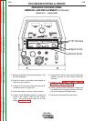
REMOTE
REMOTE
ON
ON
REMOTE
REMOTE
LOCAL
LOCAL
WELD TERMINALS
OUTPUT
CONTROL
SELECT SELECT
MPS
A
OLTS
V
MEMOR
MEMOR
Y BUTT
BUTT
ON
ON
SELECT
SELECT
ATTRIBUTE
TTRIBUTE
ADJUST
ADJUST
ATTRIBUTE
TTRIBUTE
SELECT
SELECT
KNOB
KNOB
_
+
5/16" Screws
Flathead Screws
Phillips Head
Screws