


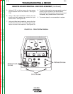

10. Remove plug J37 from the display board. See
Wiring Diagram.
11. Remove plugs J33, J333 and J331 from the
remote board.
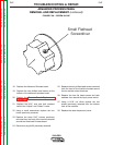
12. Using a flat head screwdriver, remove the two
mounting screws and washers from the bottom of
the remote board. See Figure F.31.
13. Remove the remote board.
14. Replace the remote board.
15. Replace the two flat head mounting screws and
washers previously removed from the bottom of
the remote board.
16. Replace plugs J331, J333, J33 and previously
removed from the remote board.
17. Replace plug J37 previously removed from the
display board.
18. Replace the four phillips head screws removed
from the front of the machine located around the
two welder output terminals.
19. Replace the two flat head screws and their wash-
ers from around the input power switch.
20. Using a 5/16” nut driver replace the two screws
previously removed from the bottom front of the
machine
21. Replace the case wraparound cover.
TROUBLESHOOTING & REPAIR
F-72 F-72
V350-PRO
Return to Section TOC Return to Section TOC Return to Section TOC Return to Section TOC
Return to Master TOC Return to Master TOC Return to Master TOC Return to Master TOC
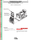
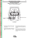
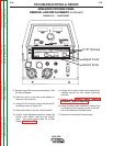
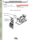
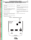
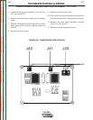
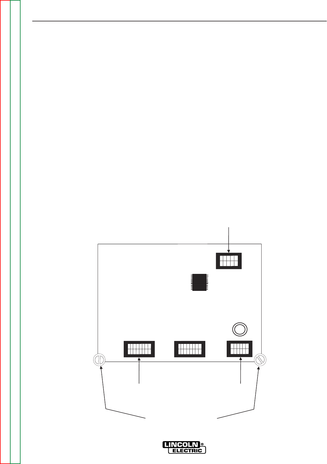
REMOTE BOARD REMOVAL AND REPLACEMENT (continued)
FIGURE F.31. – REMOTE BOARD (PLUG LOCATION)
J33
J333
J331
Remote
Board
Flathead
Mounting Screws