


OPERATION
B-6 B-6
V350-PRO
Return to Section TOC Return to Section TOC Return to Section TOC Return to Section TOC
Return to Master TOC Return to Master TOC Return to Master TOC Return to Master TOC
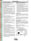
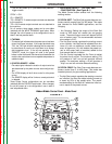
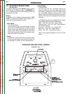
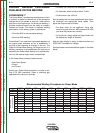
CONTROLS: (See Figure B.2.)
The MEMORY button and SELECT knob are used
together to select a welding process and store it in
memory (M1 thru M8). The SELECT knob scrolls
through the, welding process modes and memory M1
thru M8. The MEMORY button stores the welding
process in memory.
• SELECT button" (The right button) selects between
the "Hot Start" or "Arc Control". The < will indicate the
active feature shown below.
Right Digital Window
"Hot Start" (-10 to 0 +10)
"Arc Control" (0 to 10) <
• The ADJUST knob adjusts the desired settings for
the Hot Start or Arc Control feature that is active.
WELDING PROCESS MODES AVAILABLE
Stick SMAW, TIG GTAW
Gouge CAG, CV MIG GMAW
CV Flux Core, Pulse MIG
ELECTRODE MATERIAL
Steel, Metal Core, Stainless, Aluminum, Nickel
EXAMPLE OF SAVING WELDING MODES TO MEM-
ORY
The following example is how to select Pulse MIG
using .035 steel and store it into memory.
1. Turn the Select knob until welding process is dis-
played.
LEFT WINDOW RIGHT WINDOW
Pulse MIG Argon Blends
Steel .035
2. Wait two seconds and the right window will display
Arc Control on the second line on the right side.
Pulse MIG Argon Blends
Steel .035 Arc Cntrl ### <
3. SPd is displayed in the upper right Volts window.
The left Amps window matches the desired wire
feed speed that is set on the wire feeder. Adjust the
Output knob until desired number is displayed.
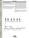
4. Start welding. If the arc length is too short turn the
Output knob up. If the arc length is too long turn the
Output knob down.
The Arc Control which is displayed in the right digital
window can be used to fine-tune the arc length and
characteristics.
5. After all adjustments have been made press and
hold the Memory button until the display changes.
The right and the left window will display what
memory to save in, lets say M1. To store in M1 push
the Memory button again to save the Pulse Mig
mode to memory M1.
6. The display in the digital windows will read as follows:
M1 Pulse MIG Argon Blends
Steel .035 Arc Cntrl 1.2
7. Saving or entering a second welding mode to a
memory, M2. Turn the Select knob until the desired
welding process mode is displayed in right digital
window. Then follow steps 1 thru 6.
Press the Memory button till the digital window
reads,
Save to MEM
M2
Press the Memory button again and the New
Welding process is saved in M2.
8. Adjust the output control to the correct wire feed set-
ting and the V350-PRO is ready to weld again.
(Note: The wire feed speed setting is not stored in
memory and will need to be reset.)
9. Adjust the Arc Control and note that the M1 goes
away indicating that the V350-PRO settings no
longer match what is stored in memory. Going back
to the original settings will not bring the M1 back.
You will need to push the Memory button to recall
the original settings in M1.
Note: After all memory’s M1 thru M8 are used and the
welder needs to store another welding process, a new
welding process will overwrite what was originally in
the memory and will read,
Save to MEM
M1 Overwrite
M1 which stored Pulse Mig is Overwritten with the new
welding process.
LN-10/DH-10 Wire Feeder Compatibility Note:
The LN-10 and DH-10 feeders can be used to pulse
weld and in the power mode with the panel. The dis-
plays on the LN-10 & DH-10 do not show the wire feed
speed or power.
8. HOT START and ARC CONTROL features
have different functions depending on the welding
Mode that is active. Each feature is described under
the welding mode heading. (See Item 7 or 7.A for
specified Mode Operations) (See Figure B.1 or B.2)