


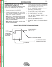

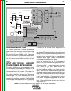
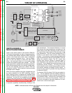
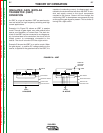

FIGURE E.2 – INPUT VOLTAGE AND PRECHARGE
Remote
Board
Mode
Panel
Display
Panel
Control Board
Choke
Positive
Output
Te rminal
Negative
Output
Te rminal
To Control
Board
Current
Feedback
Reconnect
Switch
Output Voltage Sense
Input switch
Input
Rectifier
Auxiliary
Transformer
Fan
Power
Board
14 Pin
Amphenol
6 Pin
Amphenol
Remote Control & Trigger
RS232 Supply +5VDC
SPI Supply +15VDC +5VDC
Machine Control Supply
+15VDC, -15VDC, +5VDC
40VDC
28VAC
24VAC
115VAC, 42VAC
Main Switch Board
115VAC Fan Supply
Optional Solenoid
SPI Communications & +15VDC, +5VDC Supply
Fan Control
V/F Capacitor Feedback (2)
Soft Start Control
Input Relay Control
Primary Current Feedback
IGBT Drive Signal
Primary
Current
Sensor
Primary
Current
Sensor
Output
Potentiometer
Output
Control
Weld
Terminals
Advanced
Process
Panel
RS232
12 VDC
(Not used if APP
is in place)
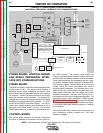
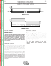
GENERAL DESCRIPTION
The Invertec V350-Pro is an inverter based welding
power source that offers multi mode constant voltage
(CV) and constant current (CC) welding and is rated at
350 amps 34VDC at a 60% duty cycle. The Invertec
V350-Pro is available in a construction version (no wire
feeder connection or auxiliary power ), a factory ver-
sion that includes a wire feeder connection and relat-
ed power, an advanced process version and a rack
version.
INPUT LINE VOLTAGE, AUXILIARY
TRANSFORMER, & PRECHARGE
The Invertec V350-Pro can be connected for a variety
of three-phase or single-phase input voltages. The ini-
tial power is applied to the V350 through a line switch
located on the front of the machine. Two phases of the
input voltage are applied to the auxiliary transformer.
The auxiliary transformer develops four different sec-
ondary voltages. The 115VAC is used to power the fan
motor and also is applied to the 14 pin amphenol type
connector for wirefeeder operation. The 24VAC and
42VAC voltages are also applied to the 14 pin amphe-
nol type connector to power wirefeeders. The 28VAC
is rectified and the resultant 40VDC is applied to the
power board.
The input voltage is rectified by the input rectifier and
the resultant DC voltage is applied to the switch board
through the reconnect switch assembly located at the
rear of the machine. The reconnect switch connect the
two pairs of input capacitors either in a parallel (lower
voltage) or series (higher voltage) configuration to
accommodate the applied input voltage.
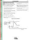
During the precharge time the DC input voltage is
applied to the input capacitors through a current limit-
ing circuit. The input capacitors are charged slowly
and current limited. A voltage to frequency converter
circuit located on the switch board monitors the
capacitor voltages. This signal is coupled to the con-
trol board (measure frequency, not voltage to check
signal). When the input capacitors have charged to an
acceptable level, the control board energizes the input
relays, that are located on the switch board, making all
of the input power, without current limiting, available
to the input capacitors. If the capacitors become
under or over voltage the control board will de-ener-
gize the input relays and the V350 output will be dis-
abled. Other possible faults may also cause the input
relays to drop out.
THEORY OF OPERATION
E-2 E-2
V350-PRO
Return to Section TOC Return to Section TOC Return to Section TOC Return to Section TOC
Return to Master TOC Return to Master TOC Return to Master TOC Return to Master TOC
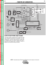
NOTE: Unshaded areas of Block Logic Diagram are the subject of discussion.