


THEORY OF OPERATION
E-4 E-4
V350-PRO
Return to Section TOC Return to Section TOC Return to Section TOC Return to Section TOC
Return to Master TOC Return to Master TOC Return to Master TOC Return to Master TOC
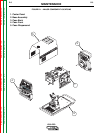
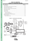
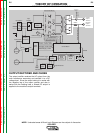
FIGURE E.4 – POWER BOARD, CONTROL BOARD
AND SERIAL PERIPHERAL INTERFACE (SPI) COMMUNICATIONS
Remote
Board
Mode
Panel
Display
Panel
Control Board
Choke
Positive
Output
Te rminal
Negative
Output
Te rminal
To Control
Board
Current
Feedback
Reconnect
Switch
Output Voltage Sense
Input switch
Input
Rectifier
Auxiliary
Transformer
Fan
Power
Board
14 Pin
Amphenol
6 Pin
Amphenol
Remote Control & Trigger
RS232 Supply +5VDC
SPI Supply +15VDC +5VDC
Machine Control Supply
+15VDC, -15VDC, +5VDC
40VDC
28VAC
24VAC
115VAC, 42VAC
Main Switch Board
115VAC Fan Supply
Optional Solenoid
SPI Communications & +15VDC, +5VDC Supply
Fan Control
V/F Capacitor Feedback (2)
Soft Start Control
Input Relay Control
Primary Current Feedback
IGBT Drive Signal
Primary
Current
Sensor
Primary
Current
Sensor
Output
Potentiometer
Output
Control
Weld
Terminals
Advanced
Process
Panel
RS232
12 VDC
(Not used if APP
is in place)
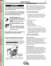
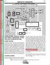
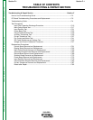
POWER BOARD, CONTROL BOARD
AND SERIAL PERIPHERAL INTER-
FACE (SPI) COMMUNICATIONS
POWER BOARD
The 28VAC auxiliary is rectified and filtered and applied
to the power board. The power board, utilizing a
switching power supply, processes the 40VDC input
and develops several regulated positive and negative
DC supplies. Three DC supplies are fed to the control
board for machine control supplies. Two positive DC
voltages are coupled to the control board for the Serial
Peripheral Communications (SPI) supplies. A +5VDC
is used for the RS232 connection supply. An over or
under input voltage detection and shutdown circuit is
also part of the power board’s circuitry. The optional
12VDC gas solenoid is powered by the remote board.
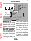
CONTROL BOARD
The control board performs the primary interfacing
functions to establish and maintain output control of
the V350 machine. The control board sends and
receives command signals from the mode or advanced
process panel, the display panel and the remote panel.
These communications are processed through a digi-
tal network called a Serial Peripheral Interface (SPI).
This network digitally communicates to and from the
control board the user’s commands and various
machine status messages. The software that is con-
tained within the control board processes and com-
pares these commands with the voltage and current
feedback information it receives from the output cur-
rent sensor and the output voltage sensing leads. The
appropriate pulse width modulation (PWM) signals
(See Pulse Width Modulation in this section) are sent
to the switch board IGBTs. In this manner, the digital-
ly controlled high-speed welding waveform is created
and regulated.
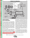
The control board also monitors the thermostats, the
main transformer primary currents and the input
capacitor voltages.
NOTE: Unshaded areas of Block Logic Diagram are the subject of discussion.