


TROUBLESHOOTING & REPAIR
F-23 F-23
V350-PRO
Return to Section TOC Return to Section TOC Return to Section TOC Return to Section TOC
Return to Master TOC Return to Master TOC Return to Master TOC Return to Master TOC
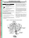
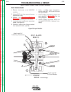
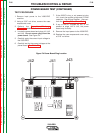
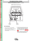
9. If the input rectifier does not meet the
acceptable readings outlined in Table F.2
the component may be faulty. Replace
Note: Before replacing the input rectifier,
check the input power switch and per-
form the Main Switch Board Test. Also
check for leaky or faulty filter capacitors.
10. If the input rectifier is good, be sure to
reconnect leads 207, 207A, and 209 to
the correct terminals and torque to 31
inch lbs. Apply silicone sealant.
11. If the input rectifier is faulty, see the
Input Rectifier Bridge Removal &
Replacement procedure.
12. Replace the case wraparound cover.
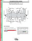
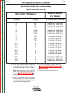
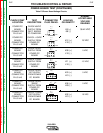
INPUT RECTIFIER TEST (CONTINUED)
Table F.2 Input Rectifier Test Points
TEST POINT TERMINALS
ANALOG METER
X10 RANGE
A
B
C
A
B
C
A
B
C
207
207
207
207A
207A
207A
209
209
209
207
207
207
207A
207A
207A
209
209
209
A
B
C
A
B
C
A
B
C
Greater than 1000 ohms
Greater than 1000 ohms
Greater than 1000 ohms
Greater than 1000 ohms
Greater than 1000 ohms
Greater than 1000 ohms
Less than 100 ohms
Less than 100 ohms
Less than 100 ohms
Less than 100 ohms
Less than 100 ohms
Less than 100 ohms
Less than 100 ohms
Less than 100 ohms
Less than 100 ohms
Greater than 1000 ohms
Greater than 1000 ohms
Greater than 1000 ohms
+ PROBE
- PROBE
Acceptable Meter Readings