


C-10 C-10
V350-PRO
Return to Section TOC Return to Section TOC Return to Section TOC Return to Section TOC
Return to Master TOC Return to Master TOC Return to Master TOC Return to Master TOC
ACCESSORIES
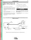
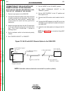
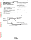
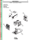
CONNECTION OF THE LN-742 TO THE
V350-PRO (SEE FIGURE C.7)
NOTE: AN LN-7 CAN ONLY BE USED WITH A FAC-
TORY OR “CE” VERSION OF THE V350-PRO.
1. Remove input power to the V350-PRO.
2. Connect the electrode cable from the LN-742 to
the “+” terminal of the welder. Connect the work
cable to the “-” terminal of the welder.
NOTE: Figure C.7 shows the electrode connected
for positive polarity. To change polarity, shut the
welder off and reverse the electrode and work
cables at the output terminals.
NOTE: Welding cable must be sized for current
and duty cycle of application.
3. Connect the K591 control cable to the 24/42VAC
14 pin amphenol on the back of the V350-PRO
and the input cable plug on the LN-742.
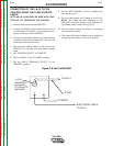
4. Set the “VOLTMETER” switch to “+” or “-”
depending on the polarity chosen.
5. Set the “MODE” to the “CV-WIRE” position..
6. Set “CONTROL SELECT” to “LOCAL”.
7. Place the “WELD TERMINALS SELECT” in the
“REMOTE” position.
8. Adjust wire feed speed at the LN-742.
9. Set the “ARC” control at “0” initially and adjust to
suit.
+ -
14 PIN
AMPHENOL
TO LN-742 INPUT
CABLE PLUG
TO WORK
K591 CONTROL CABLE
ELECTRODE CABLE
TO WIRE FEED UNIT
(24/42VAC)
AT REAR OF
MACHINE
Figure C.7 V350-PRO/LN-742 Connection Diagram