


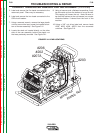
11. The back of the machine may now gently be
pulled away to gain access to the current trans-
ducer. Note: The rear of the machine cannot be
removed completely.
12. Carefully swing the rear of the machine open to
the left while facing the rear of the machine.
13. Perform the Snubber Board Removal
Procedure.
14. Remove leads #X2 and #20 from the output diode
module.
15. Remove leads #X4 and #40 from the other output
diode module.
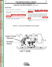
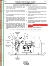
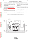
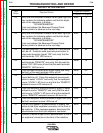
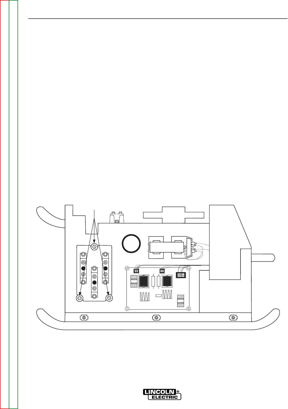
16. Using a 3/8” wrench, remove the three mounting
screws from the output diode heatsink assembly.
Take note placement of insulation for reassembly.
See Figure F.42.
17. Cut any necessary cable ties and carefully remove
the heavy lead from the diode heatsink using a
1/2” nut driver.
18. Remove the output diode heatsink assembly
through the rear of the machine.
19. Remove plug #J90 from the current transducer.
20. Using a 3/8” nut driver, remove the two mounting
nuts from the current transducer.
TROUBLESHOOTING & REPAIR
CURRENT TRANSDUCER REMOVAL AND REPLACEMENT (continued)
F-90 F-90
V350-PRO
Return to Section TOC Return to Section TOC Return to Section TOC Return to Section TOC
Return to Master TOC Return to Master TOC Return to Master TOC Return to Master TOC
3/8"
MOUNTING
BOLTS
FIGURE F.42– OUTPUT HEATSINK MOUNTING SCREW LOCATION