


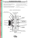

5. Label and remove the five leads connected to the
reconnect panel. Pliers may be necessary.
6. Label and remove the two leads connected to the
CB2 circuit breaker.
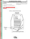
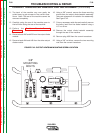
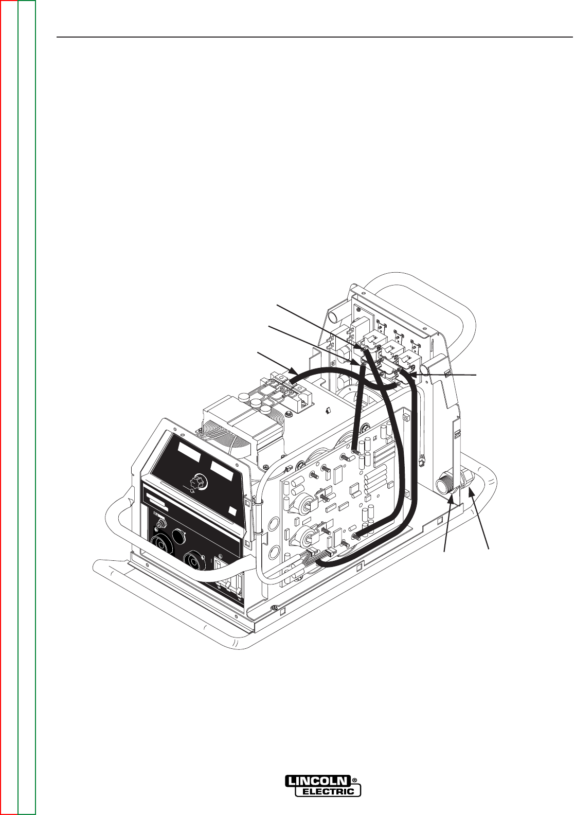
7. Using a crescent wrench, remove the large plastic
nut from around the input power line located at bot-
tom of the rear assembly. See Figure F.41.
8. Locate the steel nut located directly on the other
side of the rear assembly behind the plastic nut
that was previously removed. See Figure F.41.
9. Using a hammer and a flathead screwdriver, firmly
tap the metal nut from the bottom of one of its ribs.
This tapping will loosen the nut. Note: Be sure to
tap from the bottom so the nut loosens in a counter
clockwise fashion if viewed from the front of the
machine.
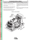
10. Using a 3/8” nut driver label and remove leads
#202, #203, #206, #207A from the reconnect
switches. See Figure F.41.
TROUBLESHOOTING & REPAIR
CURRENT TRANSDUCER REMOVAL AND REPLACEMENT (continued)
F-89 F-89
V350-PRO
Return to Section TOC Return to Section TOC Return to Section TOC Return to Section TOC
Return to Master TOC Return to Master TOC Return to Master TOC Return to Master TOC
WARNING
REMOTE
POWER
OFF
ON
A
AMPS
A
V
VOLTS
WELD TERMINALS
SELECT
OUTPUT
LINCOLN
ELECTRIC
INVERTEC V350-PRO
Metal Nut
Plastic Nut
#203
#207A
#206
#202
FIGURE F.41. LEAD LOCATIONS