


TROUBLESHOOTING AND REPAIR
FAN CONTROL AND MOTOR TEST (continued)
F-42 F-42
V350-PRO
Return to Section TOC Return to Section TOC Return to Section TOC Return to Section TOC
Return to Master TOC Return to Master TOC Return to Master TOC Return to Master TOC
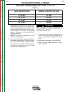
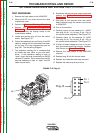
TEST PROCEDURE
1. Remove the input power to the V350-PRO
machine.
2. Using the 5/16” nut driver, remove the case
wraparound cover.
3. Perform the Input Filter Capacitor Discharge
Procedure.
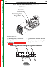
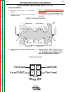
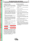
4. Locate plug J22 on the main switch board. Do
not remove the plug from the board. See
Figure F.12.
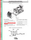
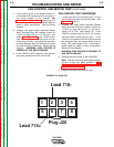
5. Carefully apply the correct input power to the
machine.
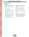
6. Carefully check for 115VAC at plug J22 pin-2
to J22 pin-3. (leads 32A to 31B(C) See Figure
F.13. WARNING: HIGH VOLTAGE IS PRE-
SENT AT THE MAIN SWITCH BOARD.
J21
J20
J22
Plug J22
Fan Lead
1
2
3
4
Lead 31B(C)
Lead 32A
Fan Lead
FIGURE F.13 PLUG J22
FIGURE F.12 PLUG J22 LOCATION