


PROCEDURE
1. Remove input power to the V350-PRO.
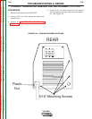
2. Using a 5/16” nut driver remove the case wrap-
around cover.
3. Perform the Input Filter Capacitor Discharge
Procedure detailed earlier in this section.
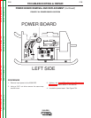
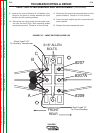
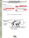
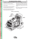
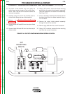
4. Locate the output diode modules located behind
the snubber board. See figure F.38.
5. Before the output rectifier modules can be
reached, the Snubber Board Removal
Procedure must be performed.
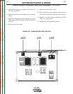
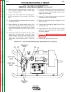
6. After the snubber board is removed, remove the
four leads connected to the modules using a 3/16”
allen wrench. These leads are #X4, #X2, #20, #40.
Note their positions for reassembly. See Figure
F.39.
7. Remove the copper plates from the tops of the
modules.
TROUBLESHOOTING & REPAIR
OUTPUT RECTIFIER MODULES
REMOVAL AND REPLACEMENT (continued)
F-84 F-84
V350-PRO
Return to Section TOC Return to Section TOC Return to Section TOC Return to Section TOC
Return to Master TOC Return to Master TOC Return to Master TOC Return to Master TOC
LEFT SIDE
Snubber
Board
Output Diode
Modules
FIGURE F.38. – OUTPUT RECTIFIER MODULE LEAD LOCATIONS