


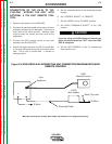
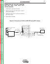
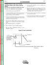


CONNECTION OF THE LN-10 TO THE
V350-PRO USING THE K1505 CONTROL
CABLE.
NOTE: AN LN-10 CAN ONLY BE USED WITH A FAC-
TORY OR “CE” VERSION OF THE V350-PRO.
1. Remove input power to the V350-PRO.
2. Connect the K1505 control cable from the LN-10
to the Invertec 24/42VAC 14 pin amphenol con-
necter on the rear of the V350-PRO.
3. Connect the electrode cable to the output terminal
of polarity required by the electrode. Connect the
work lead to the other terminal.
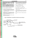
4. Set the meter polarity switch on the front of the
V350-PRO to coincide with wire feeder polarity
used.
5. Set “CONTROL SELECT” to “REMOTE”.
6. Set the “MODE” to the “CV-WIRE” position..
7. Set the “WELD TERMINALS SELECT” to the
“REMOTE” position.
8. Set the “ARC CONTROL” to the “0” position and
then adjust to suit.
9. Set wire feed speed and voltage at the LN-10.
NOTE: The voltage set point displayed on the
V350-PRO should be ignored when operating in
the remote control mode with the LN-10.
10. See the LN-10 manual for details on accessing
the control DIP switch.
11. The control DIP switch inside the LN-10 should be
set per the instructions in the LN-10 manual.
ACCESSORIES
C-11 C-11
V350-PRO
Return to Section TOC Return to Section TOC Return to Section TOC Return to Section TOC
Return to Master TOC Return to Master TOC Return to Master TOC Return to Master TOC
+ -
14 PIN
AMPHENOL
TO LN-10
TO WORK
K1505
ELECTRODE CABLE
TO LN-10
(24/42VAC)
AT REAR OF
MACHINE
Figure C.8 LN-10 V350-PRO