


ACCESSORIES
C-6 C-6
V350-PRO
Return to Section TOC Return to Section TOC Return to Section TOC Return to Section TOC
Return to Master TOC Return to Master TOC Return to Master TOC Return to Master TOC
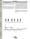
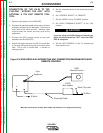
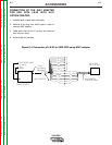
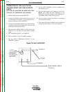
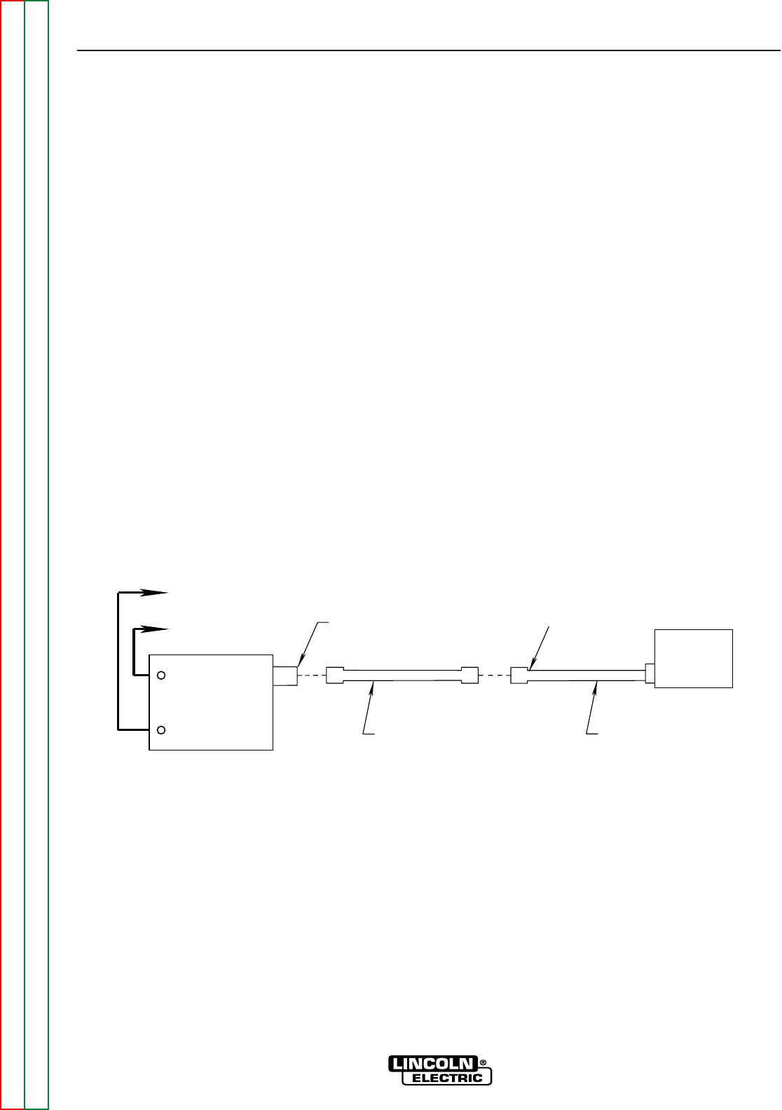
CONNECTION OF THE LN-25 WITH K431
REMOTE OPTION TO THE V350-PRO.
NOTE: AN LN-25 CAN ONLY BE USED WITH A FAC-
TORY OR “CE” VERSION OF THE V350-PRO.
1. Remove input power to the V350-PRO.
2. Connect the electrode cable to the output terminal
of polarity required by the electrode. Connect the
work lead to the other terminal. Welding cable
must be sized for current and duty cycle of the
application.
3. Attach the single lead from the LN-25 control box
to the work using the spring clip on the end of the
lead. This is only a control lead - it carries no
welding current.
4. Set the voltmeter switch to the electrode polarity
chosen.
5. Set “CONTROL SELECT” to “REMOTE”.
6. Set the “MODE” to the “CV-WIRE” position.
7. Set “WELD TERMINALS SELECT” to the
“REMOTE” position.
8. Set the “ARC CONTROL” to the “O” position and
then adjust to suit.
9. Connect the K432 remote control cable to the LN-
25.
10. Connect the K876 adapter to the K432 and to the
24/42VAC 14-pin amphenol located at the rear of
the V350-PRO.
11. Adjust the wire feed speed and voltage at the LN-
25.
NOTE: See Figure C.4 for connection Using K867
adapter.
TO
WORK
-
+
14 PIN (24/42VAC)
AMPHENOL
ELECTRODE CABLE
TO LN-25
K432 REMOTE
CONTROL CABLE
INVERTEC
POWER SOURCE
LN-25 WITH
K431 OPTION
6 PIN AMPHENOL
K876 ADAPTER
NOTE: Illustration shows electrode connected for positive polarity.
Figure C.3 LN-25 with K431 Remote Option to the V350-PRO