


Return to Section TOC Return to Section TOC Return to Section TOC Return to Section TOC
Return to Master TOC Return to Master TOC Return to Master TOC Return to Master TOC
TROUBLESHOOTING & REPAIR
F-19 F-19
V350-PRO
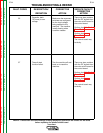
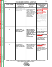
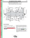
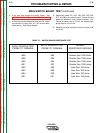
MAIN SWITCH BOARD TEST (continued)
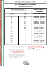
TABLE F.1. SWITCH BOARD RESISTANCE TEST
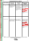
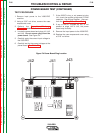
6. If any test fails replace the switch board. See
Main Switch Board Removal and Replacement.
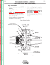
7. If the switch board resistance tests are OK, check
connections on plugs J20, J21, J22 and all asso-
ciated wiring. See wiring diagram.
8. Reconnect leads 201, 202, 203, 204, 205, 206,
207, and 208 to the switch board. Ensure that the
leads are installed in their proper locations. Pre-
Torque all leads nuts to 25 inch lbs. before tight-
ening them to 44 inch lbs.
9. Replace the case wraparound cover using a 5/16”
nut driver.
APPLY POSITIVE TEST
PROBE TO TERMINAL
APPLY NEGATIVE TEST
PROBE TO TERMINAL
NORMAL
RESISTANCE READING
+206
+208
+202
+201
+205
+203
+204
+207
-205
-203
-204
-207
-206
-208
-202
-201
Greater than 1000 ohms
Greater than 1000 ohms
Greater than 1000 ohms
Greater than 1000 ohms
Less than 100 ohms
Less than 100 ohms
Less than 100 ohms
Less than 100 ohms