


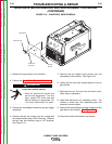
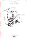
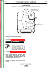
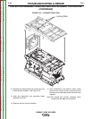
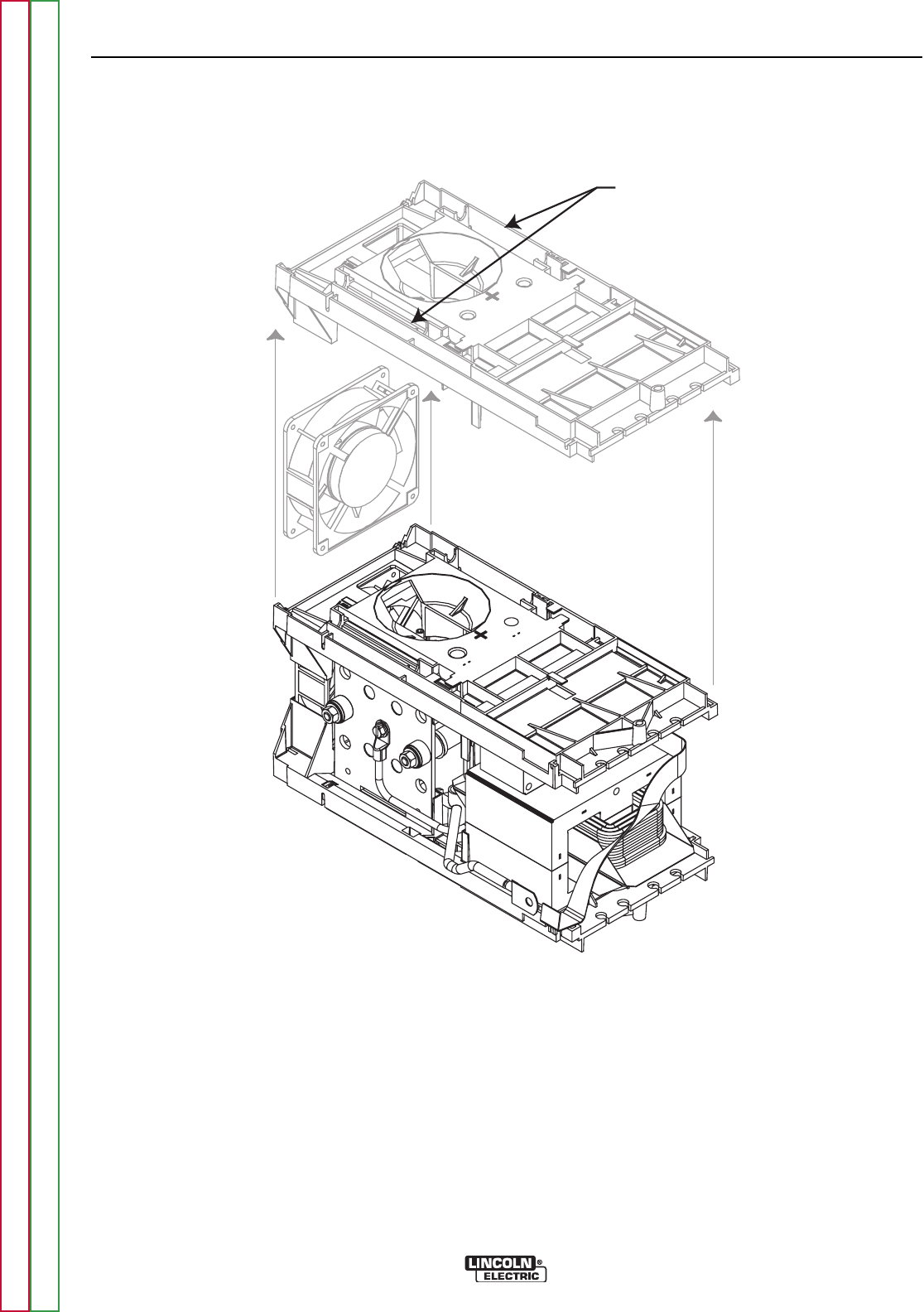
Locking Tabs
Fan
FIGURE F.18 – LOCKING TABS & FAN
FAN MOTOR ASSEMBLY REMOVAL AND REPLACEMENT PROCEDURE
(CONTINUED)
8. Depress the locking tabs and remove the top
Power Module Chassis. See Figure F.18.
9. Label and disconnect any necessary leads
attached to the Fan.
10. Remove the fan from the machine.
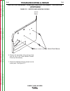
11. Upon installation of the new fan motor, make
sure that the rotation arrow is pointing up and
the flow arrow is pointing toward the front of the
machine.
Note: Fan should spin counter clockwise when
viewed from the rear of the machine.
TROUBLESHOOTING & REPAIR
F-46 F-46
COMPACT WIRE WELDERS
Return to Section TOC Return to Section TOC Return to Section TOC Return to Section TOC
Return to Master TOC Return to Master TOC Return to Master TOC Return to Master TOC