


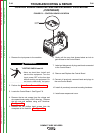

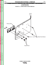

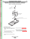

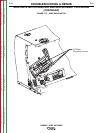
Locking Tabs
3/8” Bolted Lead
(opposite side not shown)
FIGURE F.10 – LOCKING TABS
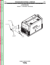
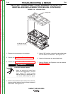
RECTIFIER, TRANSFORMER, CHOKE ASSEMBLY & CAPACITOR
REMOVAL AND REPLACEMENT PROCEDURE (CONTINUED)
TROUBLESHOOTING & REPAIR
F-34 F-34
COMPACT WIRE WELDERS
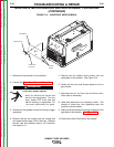
1. Remove the input power to the machine.
2. Perform the Case Cover Removal Procedure.
3. Perform the Power Module Removal Procedure.
ELECTRIC SHOCK can kill.
•
Have an electrician install and
service this equipment. Turn the
input power OFF at the fuse box
before working on equipment. Do
not touch electrically hot parts.
------------------------------------------------------------------------
4. With the Power Module removed from the machine,
depress locking tabs and remove the top chassis of
the module. See Figure F.10.
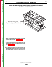
5. Using a 3/8” nutdriver, remove the two bolted leads
from the sides of the Rectifier. See Figure F.10.
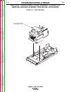
6. Label and disconnect any associated leads.
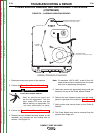
7. Remove Rectifier and Capacitor from the machine.
See Figure F.12.
WARNING
Return to Section TOC Return to Section TOC Return to Section TOC Return to Section TOC
Return to Master TOC Return to Master TOC Return to Master TOC Return to Master TOC