


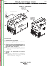
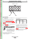


MOT-
MOT+
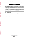
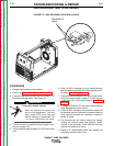
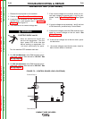
FIGURE F.3 – PLUG P3
WIRE DRIVE MOTOR TEST (CONTINUED)
TEST PROCEDURE
NOTE: POLARITY MUST BE OBSERVED FOR
THESE TESTS.
Test for correct wire drive motor armature voltage.
1. Disconnect main input power to the machine.
2. Perform the Case Cover Removal Procedure.
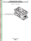
3. Locate plug P3 on the wiring harness. See Wiring
Diagram. Plug P3 is inserted into J3 on the Control
Board.
4. Locate the MOT+ and MOT- armature leads on Plug
P3. See Figure F.2.
5. Make the following voltage tests:
ELECTRIC SHOCK can kill.
•
Have an electrician install and
service this equipment. Turn the
input power OFF at the fuse box
before working on equipment. Do
not touch electrically hot parts.
a) Turn the machine off between each test.
b) Carefully insert the meter probes into the lead side
of plug P3. See Figure F.3
c) Turn the machine ON and pull the gun trigger to con-
duct the voltage test.
FROM LEAD TO LEAD
MOT+ MOT- 1.5-12.5 VDC
6. If the voltage to the wire drive motor armature is
zero, check the wires between plug P3 and the wire
drive motor.
7. If the leads and connections are good to the board,
verify the correct supply voltage 9-33 VDC at pins 1
and 10 at P3 on the control board. See Wiring
Diagram.
8. If voltage is correct at P3, the control board may be
faulty. Replace the control board.
TROUBLESHOOTING & REPAIR
F-16 F-16
COMPACT WIRE WELDERS
WARNING
Return to Section TOC Return to Section TOC Return to Section TOC Return to Section TOC
Return to Master TOC Return to Master TOC Return to Master TOC Return to Master TOC