


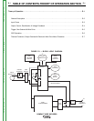
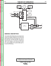

THEORY OF OPERATION
E-4 E-4
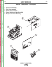
COMPACT WIRE WELDERS
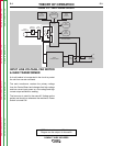
OUTPUT CONTROL,
RECTIFICATION & VOLTAGE
FEEDBACK
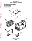
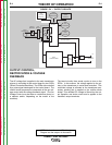
The AC voltage that is applied to the main transformer
primary is controlled at the control board by two SCRs
(Silicon Controlled Rectifiers). The SCRs are controlled
by a pulse signal developed on the control board. The
control board compares the commands of the arc volt-
age control with the voltage feedback signal. (The Arc
Voltage Control may be either a continuous control or
a selector switch, depending on the model of the
machine).
FIGURE E.4 — OUTPUT CIRCUITS
The board circuitry then sends a pulse to turn on the
SCRs. In this manner, the voltage applied to the pri-
mary of the transformer is varied and controlled. This
controlled voltage is reflected at the transformer sec-
ondary winding and is applied to the rectifier diode
bridge. This rectified DC voltage is filtered by the out-
put capacitor and choke circuit and is applied to the
machine’s output terminals.
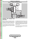
NOTE: Unshaded areas of Block Logic
Diagram are the subject of discussion
TRIGGER
RECEPTACLE
WIRE
SPEED
CONTROL
ARC
VOLTAGE
CONTROL
CONTROL
BOARD
GAS
SOLENOID
WIRE
FEED
MOTOR
LINE
SWITCH
CIRCUIT
BREAKER
INPUT
RECEPTACLE
FAN
MOTOR
MAIN
TRANSFORMER
MAIN
BRIDGE
CHOKE
+
+
-
OUTPUT
TERMINALS
VOLTAGE FEEDBACK &
MOTOR POWER
Return to Section TOC Return to Section TOC Return to Section TOC Return to Section TOC
Return to Master TOC Return to Master TOC Return to Master TOC Return to Master TOC