


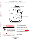

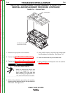

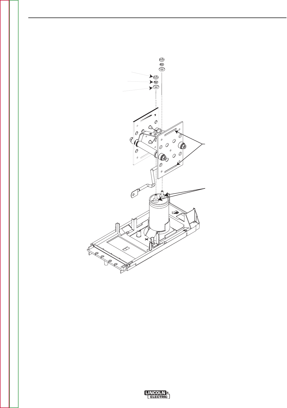
Locking Tab
Inserts
Nut
Lock W asher
Plain W asher
Dow Corning 340
(apply to contact surfaces on both term inals)
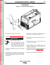
FIGURE F.12 – DOW CORNING APPLICATION AREAS
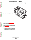
RECTIFIER, TRANSFORMER, CHOKE ASSEMBLY & CAPACITOR
REMOVAL AND REPLACEMENT PROCEDURE (CONTINUED)
TRANSFORMER AND CHOKE
11. With the Power Module removed from the
machine, remove the top chassis on the
Module.
12. Remove the two bolted leads from the sides of
the rectifier using a 3/8” nutdriver.
Note: This step may already be complete.
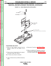
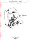
13. Label and disconnect any additional necessary
leads.
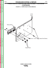
14. Remove the Transformer. See Figure F.13.
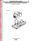
15. When re-installing the Transformer, clean the
terminal surface and apply Dow Corning 340 to
the rectifier assembly leads. See Figure F.11.
TROUBLESHOOTING & REPAIR
F-36 F-36
COMPACT WIRE WELDERS
Return to Section TOC Return to Section TOC Return to Section TOC Return to Section TOC
Return to Master TOC Return to Master TOC Return to Master TOC Return to Master TOC