


THEORY OF OPERATION
E-5 E-5
COMPACT WIRE WELDERS
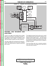
TRIGGER, GAS SOLENOID AND
WIRE DRIVE
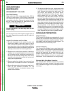
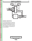
Closure of the trigger circuit (pulling the gun trigger)
signals the control board to start several functions. A
DC is applied to the gas solenoid (if present) to allow
shielding gas to flow if required. The SCRs are acti-
vated and voltage is applied to the main transformer.
The output voltage that is developed at the output ter-
minals is also fed back to the control board to facilitate
control of the output and also to power the Wire feed
Motor circuitry.
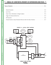
FIGURE E.5 — TRIGGER, GAS SOLENOID & WIRE DRIVE
NOTE: Unshaded areas of Block Logic
Diagram are the subject of discussion
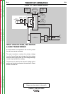
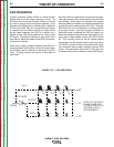
The voltage that powers the wire drive motor is varied
and controlled on the control board in response to the
setting of the Wire Speed Control. The control board
monitors the drive motor armature current and voltage
and compares the feedback information with the com-
mands sent from the wire speed control to maintain a
constant wire speed.
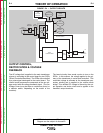
The Control Board also has an automatic protection
circuit, which shuts off the trigger circuit in the event of
a wire drive motor overload.
TRIGGER
RECEPTACLE
WIRE
SPEED
CONTROL
ARC
VOLTAGE
CONTROL
CONTROL
BOARD
GAS
SOLENOID
WIRE
FEED
MOTOR
LINE
SWITCH
CIRCUIT
BREAKER
INPUT
RECEPTACLE
FAN
MOTOR
MAIN
TRANSFORMER
MAIN
BRIDGE
CHOKE
+
+
-
OUTPUT
TERMINALS
VOLTAGE FEEDBACK &
MOTOR POWER
Return to Section TOC Return to Section TOC Return to Section TOC Return to Section TOC
Return to Master TOC Return to Master TOC Return to Master TOC Return to Master TOC