


POWER MODULE REMOVAL AND REPLACEMENT PROCEDURE
(CONTINUED)
TROUBLESHOOTING & REPAIR
F-30 F-30
COMPACT WIRE WELDERS
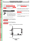
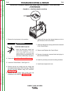
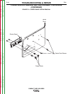
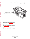
2 Phillips
Screws
4 Phillips Screws
(only found on 140c/180c models)
Phillips Handle Mount Screw
(only found on 140c/180c models)
VIEWED FROM REAR OF MACHINE
FIGURE F.8 – CASEBACK MOUNTING SCREWS
1. Disconnect main input power to the machine.
2. Perform the Case Cover Removal Procedure.
ELECTRIC SHOCK can kill.
•
Have an electrician install and
service this equipment. Turn the
input power OFF at the fuse box
before working on equipment. Do
not touch electrically hot parts.
------------------------------------------------------------------------
3. Perform the Control Board Removal Procedure.
4. Remove the two flathead mounting screws on the
caseback and depress the two locking tabs to
remove. See Figure F.8.
Note: On machines 140C & 180C, a total of four flat-
head screws must be removed from the case-
back prior to depressing locking tabs.
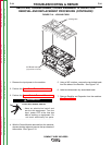
5. Label and remove the appropriate wiring and gas
hose from the top of the Power Module Chasis.
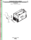
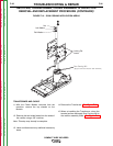
6. Remove the two flathead screws from the center
panel on right side of the machine. See Figure F.9
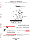
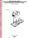
7. Note position and remove bolts on the Choke &
Rectifier.
8. The Power Module may now be removed from the
machine as a single unit.
WARNING
Return to Section TOC Return to Section TOC Return to Section TOC Return to Section TOC
Return to Master TOC Return to Master TOC Return to Master TOC Return to Master TOC