


THEORY OF OPERATION
E-3 E-3
COMPACT WIRE WELDERS
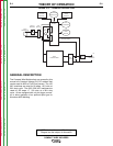
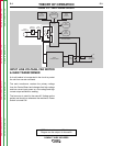
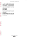
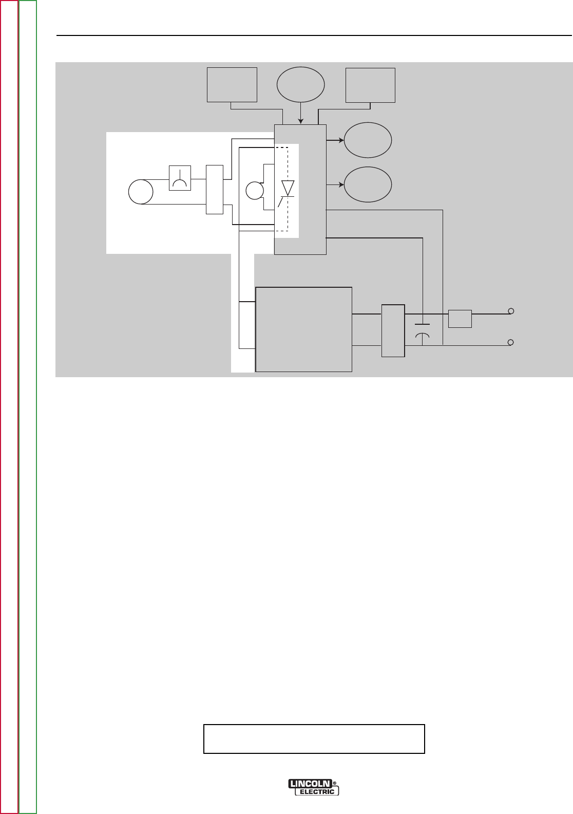
INPUT LINE VOLTAGE, FAN MOTOR
& MAIN TRANSFORMER
A circuit breaker is incorporated in the circuit to protect
the unit from current overloads.
The main transformer receives the primary voltage
from the Control Board and changes that high voltage
and low current input power to a low voltage and high
current output suitable for welding.
The fan motor is rated for the same AC Voltage as the
welder and should run whenever the machine is Power
Switch is turned ON.
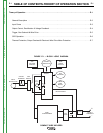
FIGURE E.3 — INPUT POWER CIRCUITS
TRIGGER
RECEPTACLE
WIRE
SPEED
CONTROL
ARC
VOLTAGE
CONTROL
CONTROL
BOARD
GAS
SOLENOID
WIRE
FEED
MOTOR
LINE
SWITCH
CIRCUIT
BREAKER
INPUT
RECEPTACLE
FAN
MOTOR
MAIN
TRANSFORMER
MAIN
BRIDGE
CHOKE
+
+
-
OUTPUT
TERMINALS
VOLTAGE FEEDBACK &
MOTOR POWER
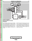
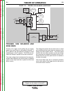
NOTE: Unshaded areas of Block Logic
Diagram are the subject of discussion
Return to Section TOC Return to Section TOC Return to Section TOC Return to Section TOC
Return to Master TOC Return to Master TOC Return to Master TOC Return to Master TOC