


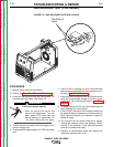
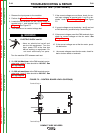
1. Remove the input power to the machine.
2. Perform the Case Cover Removal Procedure.
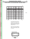
3. Locate H1 and H2 on the control board terminal
strips. See Wiring Diagram.
4. Place the voltage control to maximum.
5. Turn machine on and close trigger switch.
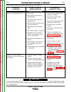
ELECTRIC SHOCK can kill.
•
Have an electrician install and
service this equipment. Turn the
input power OFF at the fuse box
before working on equipment. Do
not touch electrically hot parts.
Turn the machine OFF between each test.
------------------------------------------------------------------------
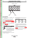
6. On 120 Volt machines you should see 120 VAC or
input voltage at H1 and H2 on the terminal strips.
7. On 230 Volt machines you should see 230 VAC or
input voltage at H1 and H2 on the terminal strips.
8. If the correct input voltage is not at H1 and H2,
check for correct input voltage at 1 and 6 and not at
H1 and H2, possible bad Control Board.
9. If the correct voltage is being applied at 1 adn 6 and
not at H1 and H2, possible bad Control Board.
Secondary Test Procedure
Note: Secondary voltages will vary proportionately
with primary input voltage. For this test, place
voltage control potentiometer to maximum.
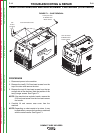
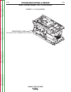
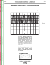
1. Locate X1 and X2. See Wiring Diagram. See
Figure F.4.
2. Isolate the two secondary leads located in the
Rectifier. Turn the machine on and close the gun
trigger.
3. On 120 Volt Machines we should see 21 VAC at X1
and X2.
4. On 230 Volt machines we should see 25 VAC at X
and X2.
5. If any of the voltages are incorrect or missing, check
for loose or broken connections. Possible bad
transformer.
MAIN TRANSFORMER TEST (CONTINUED)
TROUBLESHOOTING & REPAIR
F-18 F-18
COMPACT WIRE WELDERS
WARNING
Return to Section TOC Return to Section TOC Return to Section TOC Return to Section TOC
Return to Master TOC Return to Master TOC Return to Master TOC Return to Master TOC