


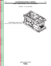
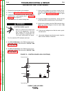
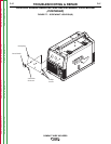


Control
Board
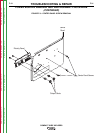
FIGURE F.6 – CONTROL BOARD LOCATION
CONTROL BOARD REMOVAL AND REPLACEMENT PROCEDURE
(CONTINUED)
TROUBLESHOOTING & REPAIR
F-26 F-26
COMPACT WIRE WELDERS
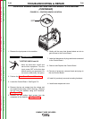
1. Remove the input power to the machine.
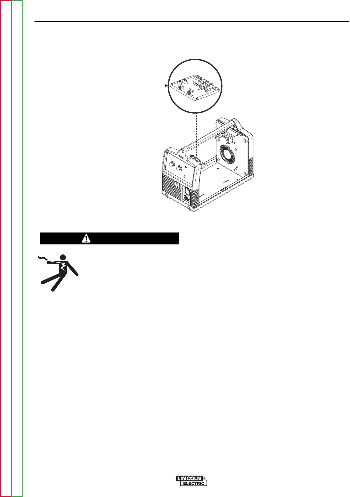
ELECTRIC SHOCK can kill.
•
Have an electrician install and
service this equipment. Turn the
input power OFF at the fuse box
before working on equipment. Do
not touch electrically hot parts.
------------------------------------------------------------------------
2. Perform the Case Cover Removal Procedure.
3. Locate the Control Board. See Figure F.6.
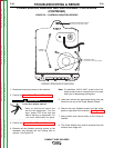
4. Remove the two set screws from the voltage and
wire speed knobs using a 5/64” allen key. Remove
the two nuts and washers using a1/2” Nutdriver.
See Figure F.7.
5. Remove the two phillips head screws from the
nameplate of the machine. See Figure F.7.
6. Gently pull the case front forward about an inch to
gain access to the Control Board.
7. Label and disconnect all plugs and leads connected
to the Control Board.
8. Remove and Replace the Control Board.
9. Connect all previously removed leads and plugs to
the new Control Board.
10. Install all previously removed mounting hardware.
11. Install case wraparound cover.
WARNING
Return to Section TOC Return to Section TOC Return to Section TOC Return to Section TOC
Return to Master TOC Return to Master TOC Return to Master TOC Return to Master TOC