


LINCOLN
ELECTRIC
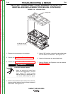
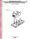
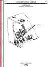
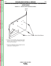
Control Knob
Nameplate
Phillips
Screws
5/64” Allen
Set Screw
FIGURE F.14 – CASEFRONT KNOB REMOVAL
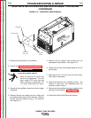
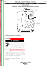
WIRE DRIVE MOTOR REMOVAL AND REPLACEMENT PROCEDURE
(CONTINUED)
TROUBLESHOOTING & REPAIR
F-40 F-40
COMPACT WIRE WELDERS
1. Remove the input power to the machine.
2. Perform the Case Cover Removal Procedure.
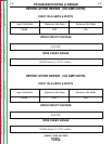
ELECTRIC SHOCK can kill.
•
Have an electrician install and
service this equipment. Turn the
input power OFF at the fuse box
before working on equipment. Do
not touch electrically hot parts.
------------------------------------------------------------------------
3. Remove the two phillips screws from the gun trigger
receptacle.
4. Remove the two set screws from the voltage and
wire speed knobs using a 5/64” allen key. Remove
the two nuts and washers using a 1/2” Nutdriver.
See Figure F.14.
5. Remove the two phillips head screws from the
nameplate of the machine. See Figure F.14.
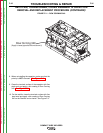
6. Gently pull the case front forward about an inch to
gain access.
7. Disconnect the air line from the wire drive motor.
Pliers may be necessary.
8. Label and disconnect any necessary leads. The
number of leads may vary depending upon the
machine’s model number.
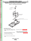
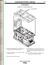
9. Remove the three phillips mounting screws from the
right side of the machine. See Figure F.15.
10. Remove the Wire Drive Motor and replace.
WARNING
Return to Section TOC Return to Section TOC Return to Section TOC Return to Section TOC
Return to Master TOC Return to Master TOC Return to Master TOC Return to Master TOC