


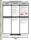
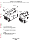
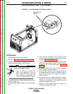
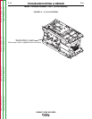
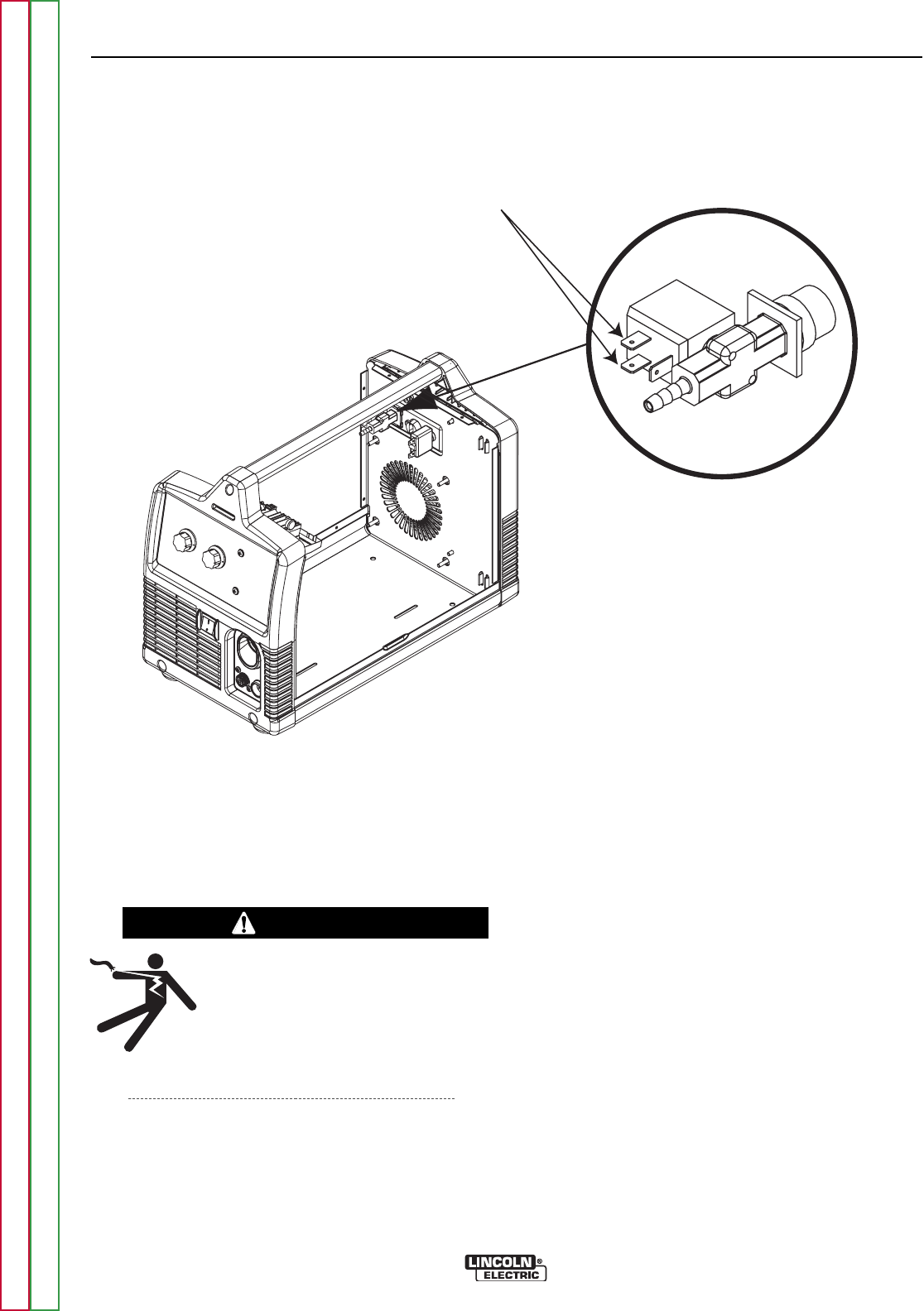
Gas Solenoid
Leads
FIGURE F.2 – GAS SOLENOID LOCATION & LEADS
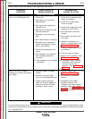
GAS SOLENOID TEST (CONTINUED)
TROUBLESHOOTING & REPAIR
F-14 F-14
COMPACT WIRE WELDERS
PROCEDURE
1. Remove input power to the machine.
2. Perform the Case Cover Removal Procedure.
3. Locate the gas solenoid and lead connections. Do
not disconnect the leads. See Figure F.2.
ELECTRIC SHOCK can kill.
•
Have an electrician install and
service this equipment. Turn the
input power OFF at the fuse box
before working on equipment. Do
not touch electrically hot parts.
4. Turn the machine on and pull the gun trigger to con-
duct the voltage test.
5. There should be approximately 6.5 VDC at the sole-
noid.
6. If the 6.5 VDC is missing or is low, check the leads
and connections between the solenoid and the con-
trol board. See Wiring Diagram.
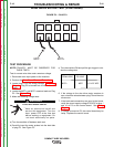
7. If the leads and connections are good to the board,
verify the correct supply voltage 9 -33 VDC at pins
1 and 10 at P3 on the control board. See Wiring
Diagram.
8. If voltage is correct at P3, the control board may be
faulty. Replace the control board.
9. If the 6.5 VDC is present at the solenoid leads and
the solenoid does not activate, the solenoid may be
faulty. Normal solenoid coil resistance is approxi-
mately 22 ohms.
10. The solenoid can be further checked by discon-
necting the solenoid leads and applying 12VDC
directly to the terminals. If the solenoid does not
activate, the solenoid is faulty.
11. Replace all disconnected leads and replace the
previously removed case cover.
WARNING
Return to Section TOC Return to Section TOC Return to Section TOC Return to Section TOC
Return to Master TOC Return to Master TOC Return to Master TOC Return to Master TOC