


MAINTENANCE
D-4 D-4
COMPACT WIRE WELDERS
GUN HANDLE PARTS
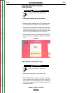
The gun handle consists of two halves that are held
together with a collar on each end. To open up the han-
dle, turn the collars approximately 60 degrees counter-
clockwise until the collar reaches a stop. Then pull the
collar off the gun handle. If the collars are difficult to
turn, position the gun handle against a corner, place a
screwdriver against the tab on the collar and give the
screwdriver a sharp blow to turn the collar past an
internal locking rib. See Figure D-3.
FIGURE D.3
„
Counter-clockwise
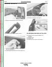
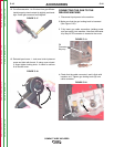
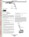
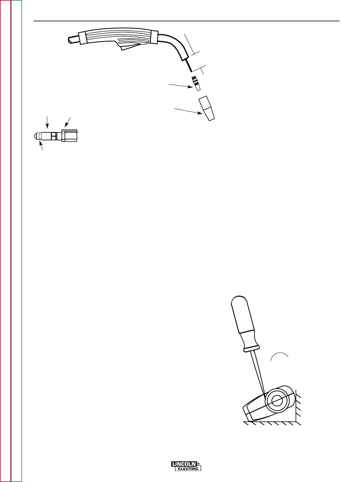
8. Screw the gas diffuser onto the end of the gun tube
and securely tighten.
9. Replace the contact tip and nozzle.
1-1/4”(31.8 mm)
Liner Trim Length
Gas Diffuser
Gas Nozzle or
Gasless Nozzle
Set Screw Brass Cable
Connector
Liner Assembly
(Liner bushing to be sealed tight
against brass cable connector)
FIGURE D.2
Liner trim length
CHANGING LINER
NOTICE: The variation in cable lengths prevents the
interchangeability of liners. Once a liner has been cut
for a particular gun, it should not be installed in anoth-
er gun unless it can meet the liner cutoff length require-
ment. Refer to Figure D.2.
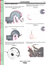
1. Remove the gas nozzle from the gun by unscrewing
counter-clockwise.
2. Remove the existing contact tip from the gun by
unscrewing counter-clockwise.
3. Remove the gas diffuser from the gun tube by
unscrewing counter-clockwise.
4. Lay the gun and cable out straight on a flat surface.
Loosen the set screw located in the brass connector
at the wire feeder end of the cable. Pull the liner out
of the cable.
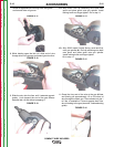
5. Insert a new untrimmed liner into the connector end
of the cable. Be sure the liner bushing is stenciled
appropriately for the wire size being used.
6. Fully seat the liner bushing into the connector.
Tighten the set screw on the brass cable connector.
At this time, the gas diffuser should not be installed
onto the end of the gun tube.
7. With the gas nozzle and diffuser removed from the
gun tube, be sure the cable is straight, and then trim
the liner to the length shown in the Figure D.2.
Remove any burrs from the end of the liner.
Return to Section TOC Return to Section TOC Return to Section TOC Return to Section TOC
Return to Master TOC Return to Master TOC Return to Master TOC Return to Master TOC