


OPERATION
B-5 B-5
COMPACT WIRE WELDERS
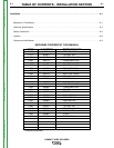
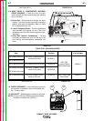
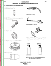
TABLE B.1
DRIVE ROLL AND WIRE GUIDES
Wire Diameter &
Type
.025”(0.6mm) MIG wire
.030”(0.8mm) MIG wire
.035”(0.9mm) MIG wire
.030”(0.8mm) flux-cored
.035”(0.9mm) flux-cored
.045”(1.1mm) flux-cored
Drive Roll
.025”/.030” (0.6mm/0.8mm)
Smooth Drive Roll
.035”(0.9mm) Smooth Drive Roll
.030”/.045” (0.8mm/1.1mm)
Knurled Drive Roll
.030”/.045” (0.8mm/1.1mm)
Knurled Drive Roll
Inner Wire Guide
.025”-.035”
(0.6mm-0.9mm)
Steel Wire Guide
.045”(1.1mm)
Steel
Wire Guide
Inner Wire Guide
Part Number
KP2531-1
KP2531-2
Drive Roll Part
Number
KP2529-1
KP2529-2
KP2529-3
KP2529-3
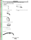
See Figure B.6
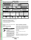
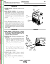
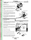
12. CIRCUIT BREAKER – If the rated input current of
the machine is exceeded this circuit breaker will
trip. Press to reset.
13. GAS INLET – Shielding gas connects to this inlet.
NOTE: Only on 125 amp machines that have added
the MIG Conversion Kit (K2525-1)
12
13
FIGURE B.6
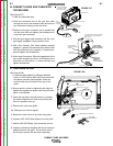
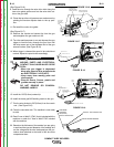
See Figure B.5a
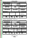
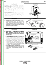
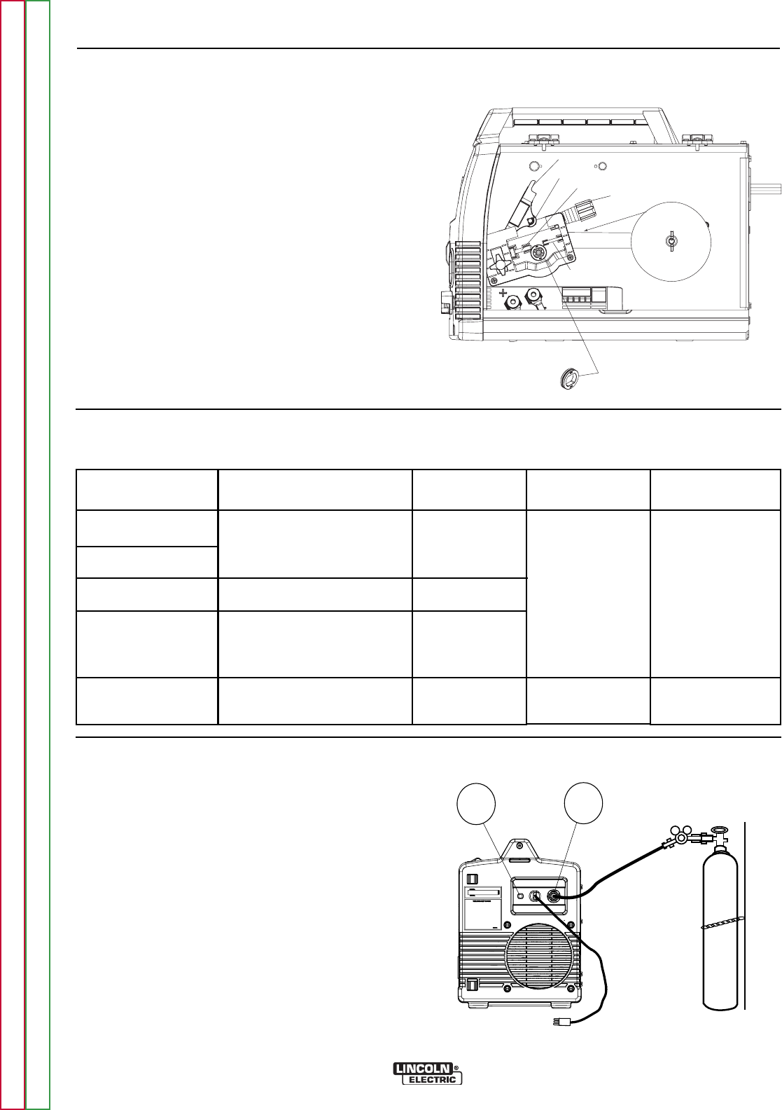
11a. WIRE DRIVE & COMPONENTS (MOLDED
DRIVE HOUSING) – Feeds wire from the wire
spool through the drive and through the welding
gun to the weld.
a. Drive Roll – Drives the wire through the drive
system. The drive roll has a groove to match the
specific wire type and diameter. Refer to Table
B.1 for available drive rolls.
b. Liner & Outgoing Guide – The liner guides the
wire between the bearing on the Pivot Arm
Assembly and Drive Roll and through the outgo-
ing guide.
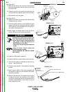
c. Drive Roll Tension Thumbscrew – Turning
clockwise increases the force on the drive roll
and turning counterclockwise decreases the
force.
WIRE SPOOL
.035" (0.9mm)
NR-211-MP
PIVOT ARM ASSEMBLY
TENSION ARM ASSEMBLY
LINER
DRIVE ROLL
OUTGOING GUIDE
BEARING
FIGURE B.5a
Return to Section TOC Return to Section TOC Return to Section TOC Return to Section TOC
Return to Master TOC Return to Master TOC Return to Master TOC Return to Master TOC