


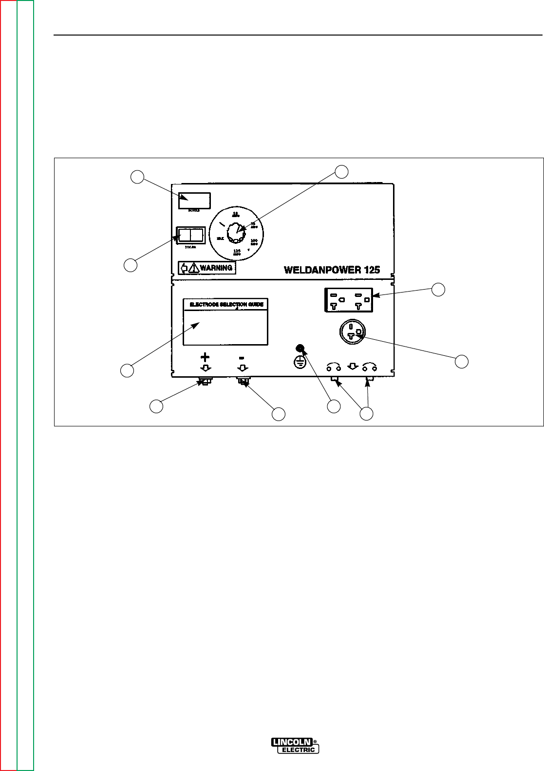
WELDER/GENERATOR CONTROLS
See Figure B.1 for the location of the following fea-
tures:
1. CURRENT CONTROL DIAL: Adjusts continuous
current output. The amperages on the dial corre-
spond to the average amperages needed for spe-
cific Lincoln welder rods.
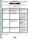
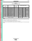
2. ELECTRODE SELECTION GUIDE: Provides rec-
ommended electrode type, size, and welder out-
put setting based on the thickness of the work.
3. WELD POSITIVE OUTPUT TERMINAL WITH 1/2 -
13 FLANGE NUT: Provides the connection point
for either the electrode holder or the work cable.
(For DC+ welding the electrode holder should be
connected to the Weld Positive Output Terminal
and the work cable to the Weld Negative Output
Terminal. For DC– welding the electrode holder
should be connected to the Weld Negative Output
Terminal and the work cable to the Weld Positive
Output Terminal.)
4. WELD NEGATIVE OUTPUT TERMINAL WITH 1/2 -
13 FLANGE NUT: Provides the connection point
for either the electrode holder or the work cable.
(For DC+ welding the electrode holder should be
connected to the Weld Positive Output Terminal
and the work cable to the Weld Negative Output
Terminal. For DC– welding the electrode holder
should be connected to the Weld Negative Output
Terminal and the work cable to the Weld Positive
Output Terminal.
OPERATION
B-4 B-4
WELDANPOWER 125
Return to Section TOC Return to Section TOC Return to Section TOC Return to Section TOC
Return to Master TOC Return to Master TOC Return to Master TOC Return to Master TOC
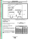
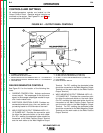
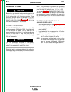
1. CURRENT CONTROL DIAL
2. ELECTRODE SELECTION GUIDE
3. WELD POSITIVE OUTPUT TERMINAL WITH 1/2 - 13 FLANGE NUT
4. WELD NEGATIVE OUTPUT TERMINAL WITH 1/2 - 13 FLANGE NUT
5. GROUND STUD
6. 20 AMP CIRCUIT BREAKERS (2) (15 AMP CSA)
7. 20 AMP, 230 VOLT RECEPTACLE (15 AMP CSA)
8. 20 AMP, 115 VOLT DUPLEX RECEPTACLE (15 AMP CSA)
9. HOUR METER
10. IDLER CONTROL SWITCH
FIGURE B.1 – OUTPUT PANEL CONTROLS
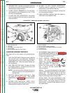
CONTROLS AND SETTINGS
All welder/generators controls are located on the
Output Control Panel. Gasoline engine controls are
mounted on the engine. See Figures B.1 and B.2 and
the explanations that follow.
9
1
10
2
3
4
5
6
7
8